VINCI
Hi-Performance
HOME
OF "VHP"
POWER PRODUCTS

| TECH AND TUNING TIPS |
VINCI
Hi-Performance |
|
||||||||||
| Home | Contact Us | About Us | Returns | Tech and Tuning Tips | Media | Project Cars | Apparel | Specialty Items | ON SALE!! | Client Cars | ||
TECH TIPS
QUESTIONS AND ANSWERS email
roger@vincicams.com
These tips are a compilation of facts from legendary Roger Vinci and other leading valvetrain experts.
We sincerely hope you can benefit from this information.
CONTENTS
Valve Train "101"
A Series of Informative Articles Introduction
Article 1
Power Improvements Associated with Quality Aftermarket Rockers.
Article 2 What
to Look For In Good Quality Aftermarket Rocker Arms.
Article 3
Stud Rockers Or Shaft Rockers / Which ones to use?
Article 4
The True Cost of
Valvetrain \Setups.
Stud Mount vs. Shaft Mount vs. Full Shaft systems
Article 5
Myths About Rocker Arm Weight
and Valve Float.
Article 6
Pretty Doesn’t Always Indicate Good – Buyer Beware, Anodized Rockers Hide a
Lot of Shortcomings.
Article 7
Cast, Vs Billet Aluminium, Vs
Steel Rockers.
Article 8
Why Is It Important To Ask Where Your Rockers
Are Manufactured And By Whom?
Article 9
Rocker Arm Geometry- made easy!
Article 10
Rocker Clearances- What Critical Areas To Inspect?
Article 11
What Causes Valve Float and How To Identify It.
Article 12
What Failures Can One Expect From Improper Rocker Geometry?
Article 13 Valvetrain Noise / Probable Causes & Checks.
Article 14
Rocker Breakage! What Typically Causes It –
Too Much Spring Pressure, Bad Geometry, Wild Camshafts?
Article 15
Impacts of Harmonics on High Performance Valvetrains
Article 16
Roller Rocker Ratios-
What Does a Ratio Change Actually Do?
Article 17 The Value Of Mixed Rocker Ratios.
Article 18 What Oils Should Be Used for Performance Valvetrains? (proper
camshaft, lifter, rocker break-in procedures)
Article 19 The Effect of Temperature On Cams and Rockers.
Article 20 Lifter Preload - Take The Guesswork Out of Preload Adjustment.
Article 21 Roller Rocker Adjustments-How Often, When and How
Article 22 Street Rockers / Street - Race Rockers / Race Only Rockers: Which
ones to use?
Article 23 Adjustable Vs. Non Adjustable - What Rocker & Lifter Combinations
Should be Used?
Article 24 Innocent Until Proven Guilty - Hi-RPM Power Failures Attributed to Roller Rockers
Article 25 Methods of Reducing
Friction in the Valvetrain
Article 26 Inspection and Servicing Yella Terra Rocker Arms
MORE VALVETRAIN TIPS
Why Leading Cam
Manufacturers
Measure “Advertised Duration” at .004” Lifter Rise
How To Compare Duration Specs Between Pushrod Cams and OHC!
Rocker Arm
Geometry
Lofting
Ignition Timing vs. Valve Timing
WHAT EXACTLY IS "LSA" OR LOBE
SEPARATION?
HOW DOES IT AFFECT THE POWER CURVE?
Cam Timing
Rocker Ratio
Valve spring height.
Does it matter?
Timing Chain Alignment
TRUCK TECH TIP
Which VHP / Crane Lifter Do I Use?
New "Premium" LS1/LS6/LS3 Dual Valve Spring, # VHP-HD-SK
New "Extra
Premium" LS1/LS3/L92 Dual Valve Spirng # VHP-XD-Sk
Can Rocker Arm “Weight, Mass, and Moment of Inertia Lead To Valve Float?
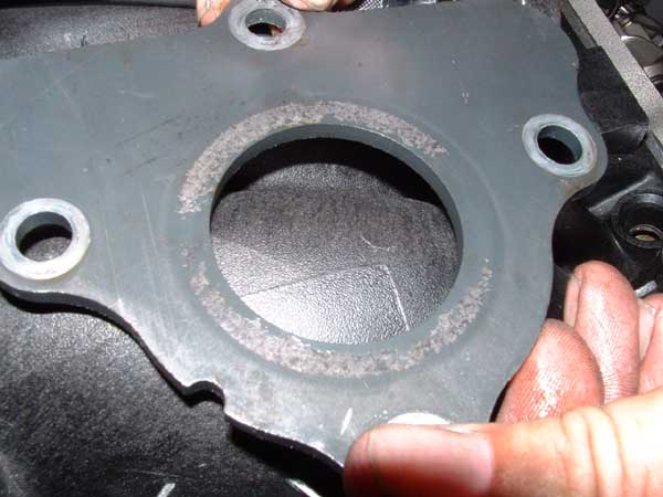
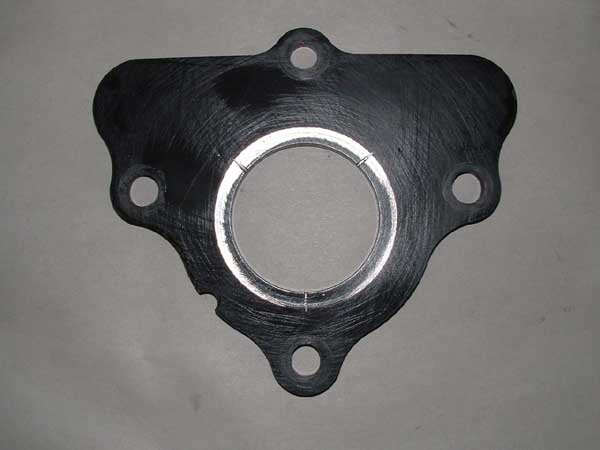
CAM
RETAINER PLATE WEAR
The Right Way
To Use Adjustable Checking Pushrods to Determine Correct Pushrod Length
Coil Bind
More On Why Our Unique New “Accelerated Lift”
Rocker Arm Geometry Makes More HP!
Most Important
Vehicle Factors in Selecting a Camshaft
Quality Steps. . . Or How Lobe-to-Lobe Accuracy
Affects HP And Durability!
Is Choosing The Right Valve
Springs for Supercharged Engines Critical?
NEW HANDHELD DIAGNOSTIC TUNER TIPS
CLUTCH
SHIELD INSTALLATION INFORMATION TIPS
Extra
Cylinder Pressure A Good Thing?
FUEL STARVATION ISSUE
Proper
Coolant Temperature and Camshaft Life!
ROCKERNOMICS
Valve Train "101"
A Series of Informative Articles
by Roger Vinci
Here are some important reasons why experienced performance engine builders choose to use "quality aftermarket rockers arms"
. As an engineer and engine builder for many years, I have often read forum posts from folks who expounded on the merits of running factory rockers for umpteen thousand miles without any problems. In fact, many of the proponents of factory rockers went so far as to denigrate aftermarket rockers. I am sure there are instances where guys have skirted by with factory rockers when engine modifications clearly indicated an aftermarket rocker arm system should be used. Car manufactures build products to a price, and so use low cost components to meet that price point. They DON'T build them for performance. The tolerances and designs have one major objective: Cost and a level of reliability to get passed their standard car warranty period. The aftermarket builds rockers that suit performance engines and if accountants were not in control ...then car manufacturer’s valvetrain engineers would build what we make!!I believe that the past 50 years of racing has proven, that for a cylinder head to breathe efficiently, the valvetrain must be rigid and strong to minimize flex, but also lightweight. For most performance applications, that means replacing the factory rocker arms, valve springs and pushrods with some type of aftermarket roller rocker arms, stiffer valve springs and stronger pushrods. This is especially important when cam specification requirements, delegate valvetrain stresses beyond the realm of factory parts. Myth! "Factory rockers are fine for modified engines".
Personally, I have seen way too many failures with factory rockers. Failures are generally a result of the rocker not being able to handle the issues created by engine modifications. Trunion bearings and trunions too weak or poorly heat treated are among the top failures. Pushrod seats badly damaged from angularity and geometry issues. Premature valve guide failures, caused by excessive side loading from factory rockers that were not designed for modified powerplants. Valve stem tip wear from excessive sliding of the factory rocker across the valve tip. All of these failures are important reasons to use "quality aftermarket rockers". There are other important reasons to use performance rockers, as well. I have consistently, seen significant power increases with the right aftermarket rocker and cam combinations. Higher ratio rockers produce more lift out of a given cam profile. Higher ratio rockers also lift the valve off the seat at a much faster rate than stock rockers to initiate and sustain increased airflow. Higher ratio rockers can also increase horsepower and torque rather than hurting torque, lowering vacuum, and reducing idle quality. Higher ratio rockers limit the lifter travel which reduces internal friction and lifter and pushrod inertia. This in turn can allow for the use of lighter valve springs due to the increased leverage effect of the high lift rocker arm upon closing the valve. These are just a few of the reasons performance engine builders choose "quality after market rockers" for their clients. Many companies now use sophisticated computer software to develop new rocker arm designs. Today’s engineers utilize a computer-aided design (CAD) program to define the basic dimensions, size, shape, length and rocker arm ratio of the rocker arm. Then we use a finite element analysis (FEA) software program to simulate loads on the rocker arm to see how well it holds up. The FEA program indicates where the greatest areas of stresses are so the rocker arm can be strengthened in critical areas if need be. Simulation software also indicates the areas of the rocker that are not under stress so additional material can be removed to lighten the rocker. By pre-testing a new rocker arm design before an actual prototype is ever built, we can optimize the rocker for the best combination of weight and strength. Next we test the rocker prototypes on extreme cam profiles and finally on actual race vehicles before the rockers ever get to the end user. By extreme cam profiles I am speaking of tall lift but very mild lobe profiles. Myth! "Long duration cam profiles are harder on rocker arms". Truth! "High lift short duration (mild) cam profiles are the most punishing to rocker arms and associated valve train". The ramps on these cams are extremely fast and straight, and tend to loft the lifter over the nose of the cam. These cams require extra spring pressure and cause extreme stress to the rockers and the remainder of the valve train. These cam profiles are often used in street applications, and should have "quality aftermarket rocker arms."Article 1 in the Yella Terra Rocker Arms 101 Series
Power Improvements Associated with Quality Aftermarket Rockers?
I have consistently seen significant power increases with the right aftermarket rocker and cam combinations. Higher ratio rockers produce more lift out of a given cam profile. Higher ratio rockers also lift the valve off the seat at a much faster rate than stock rockers to initiate and sustain increased airflow. Higher ratio rockers can also increase horsepower and torque rather than hurting torque, lowering vacuum, and reducing idle quality. Higher ratio rockers limit the lifter travel which reduces internal friction and lifter / pushrod inertia. This in turn can allow for the use of lighter valve springs due to the increased leverage effect of the high lift rocker arm upon closing the valve.
When changing rocker arm ratios on your engine to a higher ratio, not only does the gross valve lift increase, but the duration at the valve in the higher lift ranges also grows. Benefits of this geometry include increased flow into the cylinder earlier in the cycle, quicker closing of the valve to trap cylinder pressure before combustion, more effective duration at .200" net valve lift, while maintaining a relatively short seat-to-seat timing, and less required valve spring seat pressure because of the mechanical advantage of the higher seat ratio. In most dyno tested engines that had a quality set of aftermarket roller rockers installed, the power increases are quite significant. Horsepower figures increase, on average, about 14hp with same ratio rocker replacement and 25hp with higher ratio rockers. Torque figures are increased, as well, with stock ratio rockers producing an additional 12 ft lbs torque and higher ratio rockers producing 20 on average.
Article 2 in the Yella Terra "Rocker Arms 101" Series
What
to Look For In Good Quality Aftermarket Rocker Arms?
As I said in the first article, the past 50 years of racing has proven, that for a cylinder head to breathe efficiently, the valvetrain must be rigid and strong to minimize flex, but also lightweight. For most performance applications, that means replacing the factory rocker arms, valve springs and pushrods with some type of good quality aftermarket roller rocker arms, stiffer valve springs and stronger pushrods.
Certain criteria must be considered when determining the differences between good quality rocker arms and poor quality rocker arms.
What material is used in a good, quality rocker arm?
A good quality, aftermarket rocker must be made from an ultra quality
aluminum extrusion such as 2024T3500 or T6. This extrusion actually becomes
stronger as engine heat increases and is much more durable under extreme stress.
How about a poor quality rocker arm?
There are some very pretty and colorful rockers on the market that are not
made from this type of extrusion because 2024 does not anodize and polish up
very well. By comparison, a weaker extrusion that lends itself to colorful, high
luster finishing is often utilized. Anodizing actually weakens the extrusion
further. One must make a critical decision here. Pretty or strong, you be the
judge.
What about various duty requirements?
Every application does not require the same style
rocker arm. The more radical the camshaft profile, the higher the valve spring
pressure requirement. The more spring pressure required, the stronger the rocker
arm must be. A good quality rocker arm should be made available in a variety of
strengths to fit the needs of today’s engine builders.
Article 3 in the Yella Terra "Rocker Arms 101" Series
Stud Rockers vs. Shaft Rockers / Which ones to use?
With an overwhelming array of aftermarket rockers available to racers today, how do we know when to step up to the plate and invest in a shaft mount system? Basically, whenever possible, a shaft mount rocker system should always be the logical choice.
While there are some very good quality stud mount rockers in the market place, shaft mounted rockers are far and away the stronger system. No stud mount rocker arm can match the strength, rigidity, stiffness, or ability to take the rigorous punishment that a good quality shaft mount rocker arm can. When utilizing higher spring pressures and / or rapid accelerating cam lobe profiles (so popular today), a shaft mount rocker arm should be the only choice.
Article 4 in the Yella Terra "Rocker Arms 101" Series
The True Cost of Valvetrain Setups
There are many
things to consider when choosing your new roller rocker kit. Many stud mount
rocker kits bolt into the factory mounting holes. These kits are primarily non
adjustable and utilize a factory type "bolt to head system". These rockers are
normally designed to be used on stock applications where stock cams and valve
springs are retained. The cost of these kits is relatively low, but the
durability in other than stock applications is, at best, questionable.
Other stud mount rocker kits utilize screw-in studs, guide plates, and poly
locks, and require installation of these parts to permit the use of the kit.
These rockers generally need a special and often tedious adjustment procedure to
insure proper lifter preload. The cost of these kits is quite high, as they must
contain the extra parts needed to complete the installation of the kit. Although
these rocker kits are considerably stronger than the previously mentioned kits,
they in no way are as strong as shaft mount rockers and have a limited area of
use as they will flex under aggressive cam profiles and increased spring
pressures.
To help eliminate valvetrain flex, stud
mount rocker arm manufacturers have designed additional cumbersome and very
expensive stud girdles to help alleviate the flex. These girdles can be very
difficult to install and maintain.
When it’s all said and done, shaft mount rockers are still stronger, and can be
much easier to install and maintain. The cost of some of the extreme duty, full
shaft mount systems can be quite expensive. Some of these kits require serious
cylinder head modifications and machine work. In many cases the heads must be
sent into the manufacturer to be modified. But, there are also shaft mount kits
available that only require a simple bolt on procedure. These kits are much more
affordable and are designed to fit a variety of budgets and engine applications.
They are available in adjustable or non adjustable kits and are a simple bolt-on
package.
The lower cost, lighter duty kits were designed to replace stock or more mild cam and spring combinations. The higher end kits can withstand incredibly aggressive cam profiles and very high spring pressures. In either case, these rockers have a very long life span and can be easily rebuilt if the need arrises.
Contact your engine builder to be sure you choose the shaft mount rocker kit that best suits your needs.
Article 5 in the Yella Terra "Rocker Arms 101" Series
Myths About Rocker Arm Weight and Valve Float
Many people on website forums tend to think that the "weight" of the rocker arm is the cause of valve float. Unfortunately, many of the people making posts on the subject get "caught up in their underwear" because they don’t understand the difference between the terms "weight," "mass," and "moment of inertia." This misunderstanding has resulted in a great deal of misinformation being posted as fact on various web forums. A very elementary explanation of what really happens follows. If the rocker is rigid and properly designed, it should contribute very little to valve float. Weight in this case is not the prime issue, but rather the "moment of inertia" of the rocker design. "Moment of inertia" is the affect of where the mass of the rocker arm is located relative to its center of rotation. One rocker can be much heavier than another and still have a smaller moment of inertia because of where its mass is located; so weighing rockers to determine their affect of valve float is really not effective at all. (FYI: "mass" is a measure of a body’s inertia; while "weight" is the affect of gravity on "mass." "Moment of inertia" is unaffected by weight, but is affected by where "mass" is located relative to the center of rotation!) Special consideration should be made, relative to the size of the nose wheel when evaluating the moment of inertia. The smaller the nose wheel, the smaller the moment of inertia.
Article 6 in the Yella Terra "Rocker Arms 101" Series
Pretty doesn’t always indicate good – Buyer Beware, anodized rockers hide a lot of shortcomings.
Some manufacturers offer their customers roller rockers in a very pretty package. These rockers, by necessity, are made from a naturally weaker alloy than some of the not so pretty rockers. Some of the strongest extrusions available do not anodize and polish up very well. By comparison, a weaker extrusion that lends itself to colorful, high luster finishing is often utilized. Anodizing actually weakens the extrusion further. At one time, when factory rockers were somewhat crude, this type of rocker offered the buyer an alternative to the factory installed rockers. Those days are gone, in my opinion. Today’s engines are very sophisticated and can be subject to much higher stress levels than ever before. When approached with the difficult question of lowering standards in order to produce a bright shiny product rather than a strong product, some manufacturers opted to remain firm and not deviate from the stronger alloys necessary to withstand the stress levels found in today’s power plants. There are alloys that actually become stronger as engine temperatures increase. Rockers utilizing high quality, super strong alloys can be tumbled to reduce the possibility of stress risers while imparting a smooth, uniform, appearance to the rocker.
Starting with an inferior alloy and anodizing it just to make the product "look better" outside the valve cover, is an injustice to clients. It’s a pretty well accepted fact that anodizing an alloy can reduced its strength up to 50 % of its non anodized strength. One must make a critical decision here. Pretty or strong, you be the judge.
Article 7 in the Yella Terra Rocker Arms 101 Series
Cast, Vs Billet Aluminum, Vs Steel Rockers
Various engine combinations and valve train modifications call for the use of different rocker arm materials. In some factory stock or very mildly modified engine applications, the lesser expensive cast rockers can be utilized. Cast rockers are not nearly as strong or stiff as their Billet or Steel counterparts. Some manufacturers tend to use lower quality trunions and trunion bearings in their cast rockers. Always check the fine print before purchasing. Cast rockers tend to be far less aggressive than Billet Aluminum or Steel rockers therefore, valve opening rates are quite a bit slower than the rates of Billet Aluminum or Steel aftermarket rockers.
More aggressive cam profiles and / or more aggressive valve opening rates require stronger valve springs and stronger rocker arm materials. Aircraft quality Billet Aluminum and various types of high quality Steel are used in today’s highest quality aftermarket rockers.
There are distinct advantages to Billet Aluminum vs. Steel rockers.
Aluminum rockers are, of course, lighter and have the benefit of superior dampening properties over Steel rockers. If an Aluminum rocker breaks, it is normally at the trunion support area of the rocker. This only occurs when the rocker is over stressed by extreme cam profiles, demanding extreme valve spring pressures, beyond the scope of the rocker arm’s advertised properties. If breakage occurs, the Aluminum rocker arm, having sustained the damage, normally prevents further damage in the engine. Steel rockers generally force breakage onto the trunions bearings. An oil pan full of needle bearings is a bad thing. Steel rockers have an extended cycle life with a slight deflection improvement over Aluminum, but they often are heavier and harder on other valve train parts. The cost of manufacturing Steel rockers generally exceeds the cost of their Aluminum counterparts. This expense is passed onto the consumer. Some shaft mount rocker kits are manufactured in aluminum and steel, offering the consumer a choice. It is my opinion, that for most street / strip applications and many strictly race only applications, aluminum rockers are the best choice for the price.
Article 8 in the Yella Terra Rocker Arms 101 Series
Why is it important to ask where your rockers are manufactured and by whom?
It’s a pretty well accepted fact that Product Quality standards differ from country to county. Unfortunately this can also be true from manufacturer to manufacturer. In this series of articles, I have consistently remarked about the importance of the use of "good quality aftermarket rocker arms" in engine applications where
cam specification requirements delegate valvetrain stresses beyond the realm of factory parts. I also indicated a good quality, aftermarket rocker must be made from an ultra quality aluminum extrusion such as 2024T3500 or T6. I did also say that in some factory stock or very mildly modified engine applications, the lesser expensive cast rockers can be utilized. But remember, cast rockers are not nearly as strong or stiff as their Billet or Steel counterparts. Some manufacturers tend to use lower quality trunions and trunion bearings in their cast rockers.Good quality rocker arms must have replacement hardware and spares available for rebuilds and easy repair in the event either is needed. It’s no secret the more quality that goes into a product, the more comes out.
Article 9 in the Yella Terra "Rocker Arms 101" Series
Rocker Arm Geometry- made easy!
Pundits have argued the subject of rocker arm geometry for many years. These are the facts.
Besides the obvious advantage of reducing valve stem and guide wear by minimizing the "scrubbing" action that can take place when the rocker arm geometry is optimized, the maximum or advertised lift at the valve for a given camshaft profile can also be obtained. At zero lift, the rocker arm nose wheel is expected to be closer (or inboard) to the plane of the pivot point and as the valve starts moving down, the rocker arm nose wheel starts moving outboard. If the geometry is close to ideal, the rocker nose wheel will be at its most outboard position at half or mid lift at which point the rocker nose wheel starts moving inboard again as the valve reaches full lift. Simply put, ideal rocker arm geometry is achieved when the rocker nose wheel is sitting on the valve stem tip at the same position at both zero lift and full lift. Most importantly, the contact patch on the valve tip should be between .060" and .080" wide. Valve guide side loading is a result of excessive nose wheel lateral movement and not simply the position of the valve tip contact.
Differences in block deck height, head surface milling, gaskets, and other machine work can easily change rocker arm geometry. Proper installation practice demands the inspection and verification of proper rocker arm geometry.
There are two basic styles of rockers
we will deal with in this article. Stud mount and shaft mount.
On "shaft mount" style rockers, to properly dial-in the geometry, one can use shims to raise the center pivot, stand or pedestal, or mill or turn the device to reduce the height. Assorted length pedestals are available from some manufacturers. Different length pushrods may have to be used when changing pedestal height on non adjustable setups to arrive at the proper lifter preload adjustment.
Again, the important thing to remember
is in order to achieve ideal rocker arm geometry, the end result should allow
the rocker nose wheel to remain more towards the intake side of the valve tip,
NOT dead center of the valve, when the valve is closed, and the rocker nose
wheel should be sitting on the valve stem tip at the same position at both zero
lift and full lift.
A simple and proper way to indicate whether the roller tip is operating in the
proper arc on the valve stem is to place a light smear of "bearing blue"
(available at most parts stores) on the tip of the valve and carefully
assemble the rockers to the cylinder head. Rotate the engine through a few
revolutions to form a contact patch. Remove the rocker arms and you can
visualize the actual pattern the rocker nose wheels are traveling in.
Adjustments can be made and rechecked as necessary. Remember, when installing
shaft mount rockers in pairs or ganged assemblies, all stands or pedestals must
be shimmed or machined alike.
Article 10 in the Yella Terra "Rocker Arms 101" Series
Rocker Clearances- What critical areas to inspect?
Several critical
areas need to be inspected for proper rocker arm clearance, when installing
aftermarket roller rockers. Proper clearance is essential to promote valvetrain
longevity and acceptable wear patterns.
Here are some critical areas to inspect.
While most quality aftermarket roller rocker arms are designed with special clearance issues in mind, taking the time to ensure proper clearance in all of these areas will promote smooth, quiet, and safe valvetrain performance for a very long time. Ignoring proper clearance can result in a disastrous, premature end to the life of an engine.
Article 11 in the Yella Terra “Rocker Arms 101” Series
What causes valve float and how to identify It?
Just what is valve float?
“Valve float” is a common term for a situation best described as (valve train separation). This occurs due to inertia load imparted into the valve train by the action of the cam lobe against the follower. Weak valve springs are among the most common causes of valve float. Fast lobe profiles, heavy valves, etc force the need for high quality springs with increased pressure. That said, too much pressure can be disastrous to rocker arms and is often unwarranted. Forced induction is another contributor to “valve float”. Because of the increased pressure on the face of the valve, stronger springs are usually warranted.
Flex in the valve train (the majority of which is located in the pushrod) is a prime contributor to valve train separation or “valve float”. The initial loads imparted into the pushrod cause it to bend (somewhat like a pole vaulter’s pole) and then return to a straight configuration. This unloads a sharp energy pulse to the rocker arm, which transfers it into the valve/valve spring assembly. This often results in “valve lofting,” which causes the valve to operate in a different path than that described by the lobe profile. At the same time, the lifter without any load against it, can also be launched off the opening ramp of the lobe and then, as load is re-established, either: strike the nose of the lobe and eventually damage it; land on the closing ramp (like a ski jumper landing on the slope of a hill); or land on the base circle with significant and often damaging impact. If “lofting” can be controlled (by design or good fortune and the lifter lands gently on the closing ramp), it adds to area under the curve and more power. If it is uncontrolled (which happens the vast majority of the time), it can be damaging to valve train components and will compromise performance. Most of the time, power flattens out or is lost when valve train separation occurs. Again, the biggest culprit in causing this situation is the flex of the pushrod.
Many people on website forums tend to think that the “weight” of the rocker arm
is the cause of “valve float”. If the rocker is rigid and properly designed, it
should contribute very little to “valve float”. Weight in this case is not the
prime issue, but rather the “moment of inertia” of the rocker design. “Moment of
inertia” is the affect of where the mass of the rocker arm is located relative
to its center of rotation. One rocker can be much heavier than another and still
have a smaller moment of inertia because of where its mass is located; so
weighing rockers to determine their affect of valve float is really not
effective at all. (FYI: “mass” is a measure of a body’s inertia; while
“weight” is the affect of gravity on “mass.” “Moment of inertia” is unaffected
by weight, but is affected by where “mass” is located relative to the center of
rotation!). The highest quality aftermarket rocker arms are designed to be
rigid (to minimize flex), and have a very low moment of inertia relative to the
necessary strength.
Other issues are often misdiagnosed as “valve float”. These
issues can mask themselves and give the impression of “valve float”.
11 1. Coil Bind.
Increased lift causes the clearance between the valve spring
coils to diminish. The spring can become solid. The minimum recommended
clearance is .060”.
2. Additional lift can cause the pushrod
to travel a different arc. The position of the pushrod in the rocker arm cup and
or additional lift can reduce the clearance between the pushrod and the cylinder
head. If the pushrod contacts the head during its rotation, it can stall
momentarily causing the lifter to expand and pump up, holding the valve open
temporarily. The result manifests itself exactly like “valve float”.
3. Proper rocker arm clearance, that is, something interfering with the ability
of the rocker to make its full sweep can manifest itself as “valve float”.
Clearance should be checked throughout the entire sweep of the rocker arm. The
minimum recommended clearance is .60”
Understanding the issues surrounding the phenomenon of valve train separation is paramount in identifying the problem and correcting it. To ensure consistent performance and safety throughout the entire range the engine operates in, valve float must be controlled. Unchecked, valve float can and usually does, contribute to engine destruction.
Article 12 in the Yella Terra “Rocker Arms 101” Series
What failures can one expect from improper rocker geometry?
If the rocker arm contact patch is too far towards intake or exhaust side or operating in too large of an arc, creating a wide contact patch, severe rocker arm side loading can result. Here is a list of the possible failures that can result.
1.
Severe, premature, valve guide wear.
2. Premature valve stem wear.
3. Premature valve tip wear.
4. Nose wheel failure.
5. Valve stem failure at keeper grooves.
6. Uneven valve seat wear.
7. Premature valve spring fatigue.
Improper rocker geometry allowing the rocker arm to run “off center” of the valve stem tip, towards front or rear of engine can cause the following failures.
1.
Pushrod tip or cup wear.
2. Pushrod cup or adjuster wear in rocker arm.
3. Pushrod guide wear.
4. Cylinder head - pushrod hole wear.
5. Rocker stud or hold down bolt wear.
6. Poly lock wear at trunion seat area.
7. Rocker trunion at poly lock seat area wear.
Improper clearances in any of the vital areas mentioned in article 10 can cause the following failures.
1.
Rocker arm fulcrum and bearing wear.
2. Rocker stud or mounting bolt wear or breakage.
3. Valve spring retainer “outside diameter” wear.
4. Rocker arm wear at underneath area adjacent to retainer.
5. Valve spring retainer adjacent to valve seal.
6. Valve seal failure.
7. Valve guide wear at seal boss.
8. Rocker arm body near cylinder head contact points.
9. Rocker arm failure from valve spring coil bind.
10. Rocker arm failure from improper valve to piston clearance.
To avoid these failures and to ensure proper performance and longevity for your engine, always make the effort to check and correct any rocker arm geometry issues. Manufacturers of high quality aftermarket rocker arms have engineered the rockers with all of these parameters in mind, but, it is always up to the installer to properly check and fit any and all aftermarket products.
Article 13 in the Yella Terra “Rocker Arms 101” Series
Roller Rocker / Valvetrain Noise
Probable Causes & Checks
Some valvetrain noise is to be expected when moving to a high quality set of roller rockers. There are over 500 needle bearings in most roller rocker kits. Often they emit a ”sewing machine” type noise, which is harmless and quite normal. On the other hand, loud clicking, knocking, snapping or squeaking sounds are not to be tolerated. All of these sounds indicate the possibility of a serious failure is in the works.
Valvetrain noise can be caused by many improprieties. Improper rocker geometry, for instance, allowing the rocker arm to run off center of the valve stem tip towards the front or rear of engine can cause the rocker nose wheel to rattle against the valve tip. It can also cause the pushrod to enter the rocker at a severe angle forcing it to pop around in the rocker cup or contact the pushrod guideplate or cylinder head. Improper geometry can cause the rocker fulcrum to rattle against the poly lock, a problem with many stud mount rockers.
Valvetrain noise should not be associated solely with roller rockers as the most obvious culprit. Many other issues can cause noises that manifest themselves as roller rocker noise.
Insufficient clearance around the pushrod can cause contact with the head, which
causes the pushrod to loose contact with the hydraulic lifter allowing the
lifter piston to momentarily expand which in turn makes a clicking noise.
Too short a pushrod can cause the rocker to sit lower on head and contact the
stud boss.
Insufficient clearances can allow rockers to come in contact with
other parts of the valvetrain as well. These are, but not limited to, proper
clearance between rockers and valve cover and cylinder head rails.
Too little preload can cause hydraulic lifter noise. Worn lifter bores
in the block, as well as worn lifter id bores or dirty or leaky lifters can
cause valvetrain noise.
Extreme camshaft ramp speeds can also cause valvetrain noise, as the lifter has
difficulty maintaining contact with the camshaft lobe. Aggressive or poor cam
lobe designs or opening ramps with high acceleration rates can literally hammer
the valvetrain parts. The noise is similar to that of a hammer banging on an
anvil, not good. Closing ramps that are too abrupt essentially allow the lifters
to drop onto the base circle of the cam lobe with sever force, also not good.
Closing ramps should be designed to slow the valve down as it closes and set it
gently on the valve seat.
Loose
or worn camshaft bearings can allow the cam to rattle around in the block. Cam
bearings should be checked for concentricity and size when cams are installed.
Loose cam bearings are a common source of oil pressure loss.
Loose timing chain sets can emit noises that are frequently diagnosed as
valvetrain noise.
Stiff, high pressure valve springs magnify noise sources in the valvetrain. Couple this with poorly designed, aggressive cam profiles and the result is dangerous valvetrain loads and irritating, destructive noises.
Careful examination of the aforementioned information will lead to a quieter,
safer, engine with longevity being paramount.
Article 14 in the Yella Terra "Rocker Arms 101" Series
Rocker Breakage!
– What Typically Causes It – Too Much Spring Pressure, Bad Geometry, Wild
Camshafts?
Factory rocker arms were designed to run a long time
in the atmosphere of a stock engine. Subjecting them to increased spring
pressures or aggressive cam profiles can be a disaster. Trunion bearings, axles,
nose wheels, and pushrod cups can fail at any given time. Quality aftermarket
roller rockers are designed with high performance hazards figured into the
equation to help prevent these failures.
Aftermarket roller rockers can be, manufactured from a variety of materials.
Before choosing a particular rocker package, one should have a complete
understanding of the duty requirements of the rocker arms. The lower cost,
lighter duty kits were designed to replace stock or milder cam and spring
combinations. They are often manufactured from low cost, cast aluminum. They
will not stand up to the rigors of stiff valve springs or extreme camshaft ramp
speeds. The higher end kits which are made from high quality billet aluminum
like 2025 t6 for instance, can withstand incredibly aggressive cam profiles and
very high spring pressures. This particular alloy actually becomes stronger as
the temperature rises. Steel is often used in the most expensive rocker arm
kits, but it too can be subject to failure. When a steel rocker arm breaks, it
is usually in the area of the trunions or trunion bearings. An oil pan full of
needle bearings is a bad thing. While aluminum is not as strong as steel, it has
some flexibility which allows the rocker body to take much of the punishment
rather than the trunion.
Extreme camshaft ramp speeds cause the lifter to have difficulty maintaining
contact with the camshaft lobe.
This condition is often referred to as "valve float". Aggressive or poor cam
lobe designs or opening ramps with high acceleration rates can literally hammer
the rocker arms and other parts of the valvetrain. To help control this
condition, engine builders usually move up to stiffer valve springs. While this
tends to solve the immediate problem, other issues generally appear. Exceeding
the manufacturer’s recommend / allowable spring pressure is a sure way to kill
the rocker arms. When in doubt, step up to the next level rocker arm. Doing the
job twice is always painful. Determining which rocker to use for your particular
application is the responsibility of the engine builder.
High pressure valve springs cause sever loads on the pushrods.
Article 15 in the Yella Terra "Rocker Arms 101" Series
Impacts of Harmonics on High Performance Valve Trains
One of the most unknown and underrated impacts on valve train performance are the effects of harmonics. Many components of the valve train can contribute to this phenomenon. Harmonic disturbances in the valve train left unchecked can adversely affect performance and destroy parts.
Valve springs are at least as important as any other "major" performance component in an engine; yet, they are probably the most misunderstood and neglected. Incorrect or worn valve springs cause conditions that are often misdiagnosed as fuel or ignition problems. When all of the fuel and ignition system components have been replaced; and the "gremlins" are still in the engine, chances are the valve springs are either set up at the wrong tension, worn out, or just the wrong spring for the cam profile. This last factor is often the most puzzling, yet offers the greatest chance for significant improvements in engine performance. Due to their highly stressed design (valve springs are coiled from specially heat-treated, super-clean, super-sophisticated alloys of steel), valve springs have several critical characteristics that are generally called "resonant frequency" or "natural-harmonics". These are similar to those of a lead crystal goblet. By sounding a specific frequency musical note, the goblet will shatter. An "un-dampened" valve spring run at steady speed at its natural frequency will either self-destruct or lose enough of its strength and tension that it can no longer properly control the valve action. The most sophisticated valve spring manufacturers design springs with the "resonant frequency" outside of the intended operating range of the spring. This has not always been the case, especially with springs produced by the OE manufacturers for production vehicles. Highly expensive titanium valve springs have a naturally lower tendency toward harmonic disturbances, but the cost is often prohibitive.
While beehive springs reduce harmonics they do not offer the redundant protections of dual springs. Break a single spring at high rpm and the engine is lost. Break one of the dual spring and chances are you can return to a shop for a spring replacement and save the engine. Dual valve springs can lessen the effects of vibration harmonics. The springs already have a very difficult task controlling valve motion at high rpm. Add a vibration to the spring and it becomes much more difficult to maintain valve control and stability. Two springs of different thickness and shape will not vibrate at the same frequencies. Also, if one spring is in a vibration state, the spring that isn't will dampen and absorb the unwanted harmonic. Dual Rate valve springs with titanium retainers are the absolute ultimate for high performance valvetrain reliability.Lighter is better when it comes to valve spring retainers, no doubt about that.
Valve spring retainers have advanced significantly in the last few years. Titanium retainers are utilized in the highest quality performance valve spring kits, to lessen valve inertia. The smaller mass of the titanium retainer can increase the ability of the engine to achieve higher rpm. More rpm equals more horsepower. Titanium, retainers are usually made from Ti64 alloy or the higher grade Ti17 alloy. Then they are generally coated with a special hard surface coating to reduce wear.Rocker arms can contribute to valve train harmonics. Stud mount rocker arms must utilize large, stiff studs in order to prevent motion and valve train harmonics. This is not much of a problem with quality shaft mounts rocker systems. Both rocker systems must have large trunions and tight fitting bearings to control wobble and movement by the rocker arm when aggressive cam profiles and high spring pressures force large loads onto the rocker arms.
Pushrods can contribute much of the harmonic disturbance found in today’s high revving engines. Pushrod deflection creates harmonics in the valvetrain that disrupt valve timing and control causing a loss of power. It also increases the risk of the pushrod bending or breaking.
The tapered designs and large diameters of aftermarket pushrods will reduce valvetrain harmonics. Higher lift camshafts, demand stiffer springs which in turn demand stiffer pushrods. Higher lifts can also affect pushrod angularity, which in turn can cause the pushrod to contact the access hole in the cylinder head. This contact can be extremely momentary but will still affect the harmonic stability of the valve train. In more extreme cases, the contact can actually cause the pushrod to stop its natural forward movement. This pause allows the hydraulic lifter piston to expand and pump up, holding the valve open temporarily. The result manifests itself exactly like valve float.Worn lifters and / or lifter bores can contribute to valve train harmonics. The lifters internally and externally must run true. Worn lifter bores can cause the lifter to vibrate transferring the motion to the pushrod, rocker arm, and ultimately the valve. The piston in a hydraulic lifter must also run true without excessive motion. Quality lifters have unique taper tolerances in the internal bore held to less than .0003".
Timing sets can also contribute harmonic disturbances found in valve trains. The increased material strength of many aftermarket timing sets helps overcome the effects of valve train harmonics and stress. Stronger camshaft bolt kits deliver increased pre-load clamping force so you can be sure you get the accurate timing gear register that you need.
To study and measure the effects of valvetrain harmonics, the most advanced manufactures use a device called a SPINTRON. This machine can spin test mule engines up to as much as 12,000 rpm. Laser hardware and super sophisticated software can simulate real race conditions and plot valve train harmonics and failures before the products are placed in a race engine or ever sold to the end user. This helps eliminate the risk often associated with high performance products. When in doubt, always consult your engine builder for his advice. There is no substitute for experience.
Article 16 in the Yella Terra “Rocker Arms 101” Series
Roller Rocker Ratios- What Does a Ratio Change Actually Do?
First an explanation of what rocker ratio is and its significance.
Rocker arm ratio is the
ratio of the distance from the rocker arm's center of rotation to the tip
divided by the distance from the center of rotation to the point acted on by the
camshaft or pushrod. Valve lift is determined by the combination of the cam lobe
lift and the rocker arm ratio. A rocker arm ratio of 1.8 means that the actual
cam lobe lift will be multiplied by 1.8. For example, a cam lobe lift of
.347” (times) rocker ratio of 1.8 equals .625”.
Engine builders have
consistently seen significant power increases with the right aftermarket rocker
and cam combinations. Higher ratio rockers are the choice of most of the
contestants in the Engine Masters Challenge, running rocker ratios in the 2:1:1
category, year after year. Increased ratio rockers produce more lift out of a
given cam profile. They also lift the valve off the seat at a much faster rate
than stock rockers to initiate and sustain increased airflow. Higher ratio
rockers can also increase horsepower and torque rather than hurting torque,
lowering vacuum, and reducing idle quality. Increased ratio rockers limit the
lifter travel which reduces internal friction and lifter / pushrod inertia. This
in turn can allow for the use of lighter valve springs due to the increased
leverage effect of the high lift rocker arm upon closing the valve.
When changing rocker arm ratios on your engine to a higher ratio, not only does
the gross valve lift increase, but the duration at the valve in the higher lift
ranges also grows.
Because the increased ratio effectively speeds up valve movement the valve will
reach any opening height sooner than it would with a lower ratio rocker arm.
Higher ratios open the valves quicker and close the valves a little later. Since
the increase is symmetrical on either side of the cam lobe centerline, a higher
ratio will lengthen the overall valve timing making your cam act bigger.
The
effective valve open duration can be extended as much as 3 to 4 degrees,
depending on the cam type, as measured at .050″ cam lift, when the ratio is
changed from 1.7 to 1.8. While the valve lift increases but begins the lift at
the same point, the opening and closing rates are steeper. This results in the
valve reaching the .085” lift point (.050×1.7) earlier and effectively
increasing duration. In fact the duration or
time the valve is in motion from seat to seat does not change. The valve starts
to move and stops moving at the same time as with a lower rocker ratio,
(Hydraulic zero lash valvetrain.) but it does move faster and farther relative
to cam lift or lifter motion. The effect on the valve is like adding extra
degrees of duration. The cam specs don't change, nor does the actual valve
timing but the valve motion does change. The higher ratio causes valve timing to
increase proportionally as the valve opens further.
Benefits of this geometry include increased flow into the cylinder earlier in
the cycle, quicker closing of the valve to trap cylinder pressure before
combustion, more effective duration at .200" net valve lift, while maintaining a
relatively short seat-to-seat timing, and less required valve spring seat
pressure because of the mechanical advantage of the higher seat ratio. In most
dyno tested engines that had a quality set of aftermarket roller rockers
installed, the power increases are quite significant. Horsepower figures
increase, on average, about 14hp with same ratio rocker replacement and 25hp
with higher ratio rockers. Torque figures are increased, as well, with stock
ratio rockers producing an additional 12 ft lbs torque and higher ratio rockers
producing 20 on average.
The rocker ratio can change due to plasticity, that is, the capability of the
rocker arm material not being able to withstand the rigors of aggressive lobe
profiles and higher spring pressures. The rocker arm can actually deflect during
the lift cycle which reduces the effective ratio. This result is the rocker
failing to reach full lift. It is very important to ascertain the material your
rocker arm choice is
made from. Inexpensive cast and or stamped rocker arms just won’t
cut it when you exceed the factory specs with aggressive cam profiles or high
spring pressures, Always opt for a high quality billet aluminum or steel rocker
arm to insure proper geometry and valvetrain longevity.
Other areas of concern are the
trunion and trunion bearings. They must be extremely strong and the fit must be
held to tight tolerances, to insure the rocker arm can operate through its full
cycle without lost motion. Factory rockers with flimsy or worn trunions and
bearings are guilty of this action.
Not to further confuse the issue, but another important note is that the rocker
arm ratio is always changing because the rocker arm tip is moving on an arc
around it's center pivot point, but the valve stem goes straight up and down.
This means that as the rocker arm moves, the distance from the pivot point to
the contact point on the valve stem is always changing. If this distance is
changing, the rocker ratio is also changing. Typically, the amount of change for
a nominal 1.7 rocker ratio in a pushrod engine is from 1.65 to 1.75 as it goes
through its arc. This is one more reason to increase rocker arm ratio, to help
offset the lower end ratio effect.
There are some possible negative effects and cures that must be considered when
using higher ratio rocker arms. Higher ratios put a greater load on the
pushrods! Therefore, stiffer pushrods should always be used in conjunction with
higher ratio rocker arms. Higher rocker ratio rockers move the pushrod cup
closer to the trunnion of the rocker causing possible interference issues with
some cylinder heads. Increased rocker arm ratios increase gross valve lift,
which in turn reduces spring coil bind clearance, retainer to seal clearance and
piston to valve clearance. To prevent negative effects, ensure all valve train
clearances are sufficient to support the higher ratio rocker system.
Article 17 in the Yella Terra “Rocker Arms 101”
Series
The Value of Mixed
Rocker Ratios
The debate over the optimum rocker-arm ratio has dragged on probably since the invention of the pushrod V-8. One important factor is, factory engine manufacturers generally build their rockers with a less than advertised in true rocker ratio. That is to say, a typical factory rocker arm rated at 1.7 to 1 when measured with a dial indicator can actually be less than advertised. I have seen them as low as 1.66 to 1. Utilizing a quality aftermarket roller rocker system can bring the ratio back to advertised ratio or increase it on the intake and / or exhaust side.
A terrific tuning aide many engine builders and tuners consistently use is testing an engine’s combination performance by mixing rocker arm ratios. It is considerably easier to swap rocker arms than camshafts. Some engine combinations respond very favorably to added lift on the intake or exhaust side of the engine. Often with stock heads even ported, the exhaust side really doesn’t flow as well as it should. The inlet and exhaust paths are viewed as a restriction to the cylinder and the flow capability varies depending on the cross-section and bowl geometry. A cylinder is a displaced volume that sees flow movement and accelerations based on the stroke, bore, and rod geometry. One can run either a dual pattern cam with more lift on the exhaust side, or higher ratio rockers on the exhaust side. In many cases, the exhaust side needs a chance to get rid of the combusted charge and help start the intake flow into the cylinder. Additionally, a dual pattern cam that is heavily biased to the exhaust with wider and earlier events can be balanced out a little bit with the larger ratio on the intake. This would be very advantageous in a lower intake capability motor that does not need all the exhaust flow capability and it could just as easy be effective on single (or similar) pattern camshaft too. It all depends on the particulars of the specific combination. As far as rocker arm ratios are concerned, there are no rules set in stone. Every case has to be analyzed on its own.
On supercharged or nitrous assisted engines, many tuners have profited from running a higher lift on the exhaust rocker, than the intake. Because the intake side of modern engines is generally more efficient than the exhaust side and the supercharger or nitrous charge is being forced into the combustion chamber, there is a far greater demand to rid the chamber of the spent charge to make room for the incoming charge. While a cam change may very well be in order, a rocker arm ratio change is simple, effective, far less costly and time consuming. If the results are positive, a cam change would probably be called for.
Some of the more savvy manufacturers understand the value of mixed rocker ratios and actually offer rocker arms in half sets to enable the engine builder to comfortably create mixed ratio sets.
Article 18 in
the Yella Terra “Rocker Arms 101” Series
What oils should be used for high performance valvetrains?
Are there different oils recommended for Flat Tappet and Roller applications?
Lubrication!
Your engine can’t live without it. There are very different theories when it
comes to which oil should be used with flat tappet cams and roller camshafts.
While some agree to disagree, the following facts are pretty well unanimously
accepted in the performance industry today.
When dealing with flat tappet cams, an extremely high quality break-in oil is
imperative to allow proper break- in. Never, use a “multi vis” or synthetic oil
for break-in purposes with flat tappet cams. Flat tappet cams must have high
quantities of the anti-scuffing additives Zinc and Phosphorus to counteract the
forces of metal to metal contact that prevent the proper break-in sequence. The
recent government required reductions in these additives in standard oils
present serious problems for flat tappet camshafts. Yesterday’s oils had much
larger quantities of these additives which helped enormously in the break-in
procedure. The Zinc and Phosphorus content in today’s “off-the-shelf” oils have
been reduced upwards of 20% since 2001 and approximately 35% since 1997). In
terms of oil selection, manufacturers recommend a high “ZDDP”, Zinc Dialkyl
Dithiosphosphate, content oil for the break-in procedure and regular operation.
There are several companies that are now offering specialized “race/off-road”
oils, high in anti-friction and anti-wear content, to combat this specific
problem. These oils carry the SL rating and contain up to 1000 ppm of Zinc and
Phosphorous.
There are very articulate methods for break-in procedure camshaft
manufacturers demand today to ensure the camshaft and lifters mate properly.
Many manufactures insist on the use of very light valve springs during the
procedure and then replacing them with the recommended stiffer springs when the
break-in procedure is completed. Lifters should not be prefilled with oil, as
this tends to hold the valves open which requires additional time to start the
engine. The camshaft and lifters must be coated with a special break-in paste
assembly lube recommended by the manufacturer. This paste contains extremely
high quantities of Lithium Molybdenum Disulfide, an anti wear compound packaged
in most flat tappet cam kits. Care should be taken to rotate the engine as few
times as possible to ensure the coating stays on the cam and lifters. The oil
pump should be primed. Timing should be pre-set and carburetors pre-filled with
fuel, to eliminate unnecessary engine rotation during startup. Once the engine
is started, it should be revved up to 3000 rpm “quickly” and varied from 1500 to
3000 rpm continually for 30 minutes. The increased, oscillating rpm provides
adequate oiling of the cam and lifters while ensuring a ” lean-out” condition
does not occur from holding the engine at a constant high vacuum rpm. Be sure
the timing is advanced adequately to prevent excessive engine loading and heat
during the break-in procedure.
Once the procedure is finished, the break-in oil should be drained,
filter changed, and a high quality 30wt non synthetic oil put back in the
engine. Next the proper tension valve springs should be installed. After 500
miles the oil and filter should again be changed. At this time a high quality
non synthetic oil with a viscosity rating of not less than 10w 40 should again
be used. Most flat tappet cam manufacturers do not recommend using synthetic
oils at any time. Not following a proper break-in procedure will surely cause
premature camshaft / lifter failure, and most manufacturers will not warranty an
improperly broken in camshaft.
When dealing with roller camshafts and roller lifters, special
break-in oil is unnecessary since no break-in is required. The same applies to
roller rockers. On non-catalytic converter applications, use petroleum based SE,
SF, SG grade, oil. On catalytic converter applications, use a premium, petroleum
based oil, with a viscosity rating of not less than 10w 40. An API rating of SL
or SM is required. Be sure to fill the new oil filter with oil before installing
it. .
No break-in paste type compounds, like the ones used with flat tappet cams, should be applied to the roller camshaft, or roller lifters, just a formidable amount of the same high quality oil used in the engine. The pushrod cups in roller rocker arms and valve stem tips should be coated with a lithium molybdenum assembly lube to help alleviate scuffing during initial start up, while lifters and pushrods are filling with oil. An ample supply of a premium, petroleum based oil, with a viscosity rating of not less than 10w 40, should be used to lubricate the roller lifters, and roller rocker arms. Again, most roller cam and roller rocker arm manufacturers so not advocate the use of synthetic oil during the initial run-in period.
When first starting the engine
hold the rpm to a fast idle while lifters are filling. It is not uncommon for
the lifters to require proper filling and emit some noise during the initial
start-up. I have found that running the engine for a few minutes and then
shutting it down for 10 minutes will often allow the lifters to bleed and
balance themselves. Upon restart, the loose lifter noise is usually gone. Any
performance engine equipped with a roller cam and / or roller rockers should be
treated with the very best oil one can afford. Change oil and filter regularly.
Heavier weight oils tend to quiet the sometimes sewing machine noise associated
with roller rockers and do afford more protection than lighter weight oils.
Most roller rocker arm manufacturers do not advocate the restriction of oil to
the top of the engine, a practice of many engine builders. This procedure not
only restricts lubrication to the rockers, but also under high stress conditions
oil directed from the rocker arms splashing on the valve springs has an
important cooling effect on the springs. Restricting the oil supply to the
valvetrain can interfere with this process. My advice, be cautious when limiting
the oil supply anywhere in your engine. When in doubt, seek the advice of the
manufacturer.
Article 19 in
the Yella Terra “Rocker Arms 101” Series
Rockers and Cams- How do they behave in high temp environment?
One
major effect high engine temperature has on both, rocker arms and camshafts is
the “valve lash” or clearance between the rocker arm and the tip of the valve,
associated with solid lifter type valvetrain. Engine temperature will alter the
clearance between the valve tip and rocker arm tip. Standard sliding type of
rocker tips associated with most production engines or aftermarket roller
rockers with a roller nose wheel at the tip are subject to engine temperature
changes. There is very little to be concerned about when the engine is equipped
with hydraulic lifters as the amount of lifter preload far exceeds the range of
clearance change from the increase or decrease in engine temperature.
This is not the case, however, with solid lifter camshafts. Depending on the
block and head material as well as rocker arm material, the changes in valve
lash can be quite significant. For instance when dealing with an iron block and
iron heads, the valve lash can decrease by as much as .002” as the temperature
increases from ambient to its normal operating temperature. Therefore the valve
lash should be set .002 looser than the specifications call for. With an iron
block and aluminum heads, the valve lash can increase, on average, by about
.006” as the temperature increases from ambient to its normal operating
temperature. The aluminum heads expand more than the iron heads. Therefore the
valve lash should be set .006 tighter than the specifications call for. Care
must be exercised because tightening the valve lash can reduce idle quality
during warm up.
A more serious effect temperature can have on aftermarket aluminum rocker arms is deformation. Some alloys have properties that allow them to be color anodized and beautifully polished to a jewel like consistency. The problem is, these alloys generally have a much lower tolerance to temperature and actually begin to lose strength and deform well before they reach operating temperatures in modern street machines and race engines. My advice, take a good long look at the pretty stuff, then invest your money in perhaps a not so pretty product that maintains it strength throughout the operating temperature range of the engine. Some alloys, like 2024T6 actually grow stronger as the temperature rises. Check with you rocker arm manufacturer to see what alloy they are using. Remember, once the rocker cover is installed, the view is gone and the performance of the product is paramount.
Article 20
in the Yella
Terra “Rocker Arms 101” Series
Lifter Preload
Take the guesswork out of preload
adjustment.
LS Series Engines with Yella Terra Ultralite Rockers
Yella Terra ultralite rockers are truly an Easy Fit product, and will bolt on most factory stock engine applications without any modifications. If however, a camshaft with a smaller base circle has been installed, or the cylinder heads have been removed, milled, or replaced with aftermarket heads or gaskets, lifter preload can become an issue with stock or aftermarket rockers. Yella Terra developed this lifter preload instruction manual to help you arrive at the proper lifter preload depth.
1) Yella Terra suggests using a lifter preload depth of .060 to .090 to achieve proper preload on LS Series engines with hydraulic roller lifters. We will be using the outside figure of .090 for our illustration.
2) Stock rocker retaining bolts and the Ultralite retaining bolts are 8mm x 1.25. The bolts move .047” for each revolution; therefore, two turns would represent .094” depth, slightly over the maximum desired preload.
3) Utilizing stock 7.400”pushrod for measuring purposes is a good starting point.
4) Install a set of Yella Terra Ultralite rockers on the checking cylinder. Torque them to 22 lb./ft.
5) Ensure the cam is at its base circle by turning the engine over, by hand, and as exhaust valve just starts to open, the intake lifter will be on the base circle of the cam and lash/preload should be checked for that intake valve. The exhaust lifter preload will be within a few thousandths of the intake lifter preload.
6)
Back off rocker retaining bolts until rockers are loose on
valves. Run rocker retaining bolts down together, carefully until “zero lash”
has been achieved, on intake valve. This is easily done with your fingers "wiggling" the rocker back
and forth while tightening the bolts. Pay attention
to the nose wheel contacting the valve tip.
The point, at which the "slack" is just gone, is zero lash. No pressure
should be applied to the “checking” valve tip when locating “zero lash”. Only
the clearance “lash” should be removed.
Set your torque wrench to 22 lb./ft. Tighten both rocker
retaining bolts to
full torque and count the number of turns it takes the bolts to move from “zero
lash” to full torque.
7) We are looking for 1.5 turns (.070”) to place the preload in a desirable zone. Any amount that exceeds 1.5 turns could potentially over preload the lifter.
8) Subtract amount of extra turns from stock 7.400 pushrod length.
9) Example: The bolts rotate 2.0 times. The additional ½ turn of preload is approximately .023”. You would want a pushrod that is .025” shorter than stock or 7.375”.(7.400”-0.025”)
10) Likewise, any amount that is less than 1.25 turns is under preloading the lifter.
11) Add the desired length to the stock pushrod length.
12) Example: The bolts rotate 1.0 time. The lack of preload is approximately ½ turn or .023”. You would want a pushrod that is .025” longer than stock or 7.425”. (7.400 + 0.025”)
13) Again, is not necessary to check preload on other lifters because they should all be within a few thousandths of each other.
14) Please note, the rocker kit contains .020” thick shims to help facilitate proper rocker arm geometry. They are not to be used for lifter preload adjustment.
"QUICK REFERENCE CHART"
STOCK PUSHROD is 7.400 0.60 - 0.90 operating range
Set at 22 Lbs
Looking for 1.5 turns and click 1.5 x 0.047 movement 0.70 total
Two turns and then click 2 X 0.047 movement 0.094 (too much)
More than 1.5 turns Over Preload Need Shorter pushrods or Use Spacers
1.0 to 1.5 turns Preload Set Properly
Less than 1.0 under preloading lifter Need Longer pushrods
Article 21 in the Yella Terra “Rocker Arms 101” Series
Roller Rocker Adjustments – How Often, When and How?
Pushrods? Shims? Pedestals? Lash Caps?
This article will deal with adjusting the rocker arms solely for the purpose of
acquiring lifter preload or valve lash. For an in depth explanation of rocker
arm’s adjustment as it pertains to proper geometry, please see article no. 9 in
the series,
“ Rocker Arm Geometry- Made Easy ”
Many owners who drive vehicles equipped with performance engines wonder how often they should adjust their roller rocker arms. There is no simple answer. Under normal driving conditions with hydraulic lifters and milder street style camshafts, further adjustments should be pretty much unnecessary. This is only true if the original adjustment included the proper lifter preload calculations. Occasionally a lifter will develop an internal wear problem causing it to emit a clicking noise. Frequently this can be alleviated by adjusting the preload a bit deeper with the rocker arm.
Subjecting the rockers to increased spring pressures and / or aggressive cam profiles can cause them to loosen. Quality aftermarket roller rockers are designed with high performance hazards figured into the equation to help prevent this from happening. Aggressive or poor cam lobe designs and / or opening ramps with high acceleration rates can literally hammer the rocker arms and other parts of the valvetrain. To help control this condition, engine builders usually move up to stiffer valve springs. While this tends to solve the immediate problem, other issues generally appear. Exceeding the manufacturer’s recommended, allowable spring pressure is a sure way to kill the rocker arms, or at the least, cause them to loosen up and allow the lifters to lose preload. This results in valvetrain noise which can often be corrected by re-adjusting the rockers.
Adjustable stud mount rockers utilize an adjuster nut or poly lock on the
mounting stud to secure the rocker. While this system is perhaps the easiest to
adjust lifter preload or valve lash, it is much less stable than shaft mount
rocker systems and will not withstand the loads produced by today’s aggressive
camshaft profiles or higher pressure spring sets.
When utilizing a shaft mount rocker system, appropriate installation techniques
must be employed to ensure the proper function and longevity of the rocker
system. Torque specifications must be followed to the tee, especially on newer
alloy heads to guarantee hold down bolts remain tight and threads stay intact.
High quality roller rockers manufactured from high quality ally extrusion such
as 2024T6 are far less prone to losing their adjustment. Inferior rockers,
specifically Asian made with inferior cast aluminum not only tend to lose their
adjustment, but also cannot stand up to the rigors of today’s performance
requirements. Beware of the “best bang for the buck theory”. The “bang” may end
up being emitted from your valvetrain.
There are many different concepts and styles of valvetrain hardware that cause a
particular method of adjusting the lash or lifter preload to be followed.
Besides the most common rocker adjustable styles, there are systems that utilize
shims, lash caps, pedestals and pushrods to calibrate the proper valve lash or
lifter preload. The pushrods are probably the most common method of adjusting
lifter preload in hydraulic lifter systems, by altering their length. Longer
pushrods create more preload and vice versa. Shims placed under rocker stands or
pedestals in shaft mount rocker systems can be used to adjust lash but can also
affect rocker geometry. The same applies to machining the stands or pedestals to
shorten them. Rule of thumb suggests utilizing a roller rocker system that
incorporates a threaded pushrod adjuster or cup adjuster to calibrate the valve
lash, whenever possible. This type of system will have little effect on the
rocker arm geometry, so long as the cup adjuster is kept within manufacturers
specs. Care must be taken to follow manufacturer’s recommended allowable
distance that the adjuster can be moved off the rocker seat to ensure the
adjuster is not subjected to extreme loads. Generally two turns out from the
seat is the maximum distance recommended by most manufacturers. Utilizing a
proper length pushrod in combination with the rocker adjuster minimizes the
stress on the adjuster. Many manufacturers provide light valve springs and
adjustable pushrods to help facilitate proper lifter preload or valve lash.
In engines equipped with solid roller camshafts, the need for valve lash /
rocker adjustment is more common. The constant pounding of the rocker against
the valve stem causes shock and wear which imminently necessitates more frequent
rocker adjustments. Proper lash adjustment ensures maximum camshaft performance
and valvetrain longevity.
Engine blocks or cylinder heads that have been surfaced or non factory head
gaskets can alter the required lash or lifter preload measurements. Valve jobs
tend to sink the valves deeper in the valve pockets, which increases the preload
or reduces the lash.
Lash caps are little hats that fit over the valve stem. They are often used on SOHC and DOHC applications, which have no pushrods, to facilitate valve adjustment. On OHV applications “pushrod engines” they are not often used, however, one purpose is to increase the durability of the valve stem when using valves without hardened tips. Another purpose is to lengthen the valves to achieve better rocker arm geometry when the valve stems are too short. Here’s the catch. Lash caps add unwanted weight to the valve, as much as 10 to 15 grams. One should never add weight to the valve stem or rocker tip, if at all possible. It increases the likelihood of valve float, which necessitates the use of stiffer springs. Lash caps can and often do come off the valve stem. They have an uncanny ability of finding their way into the oil pan. Generally speaking, I never use lash caps unless there is no other way to correct a problem.
Article 22 in the Yella Terra “Rocker Arms 101” Series
Street Rockers / Street - Race Rockers / Race Only Rockers
which ones to use?
Definitions:
1)
Street Rocker
Generally, lowest cost rocker in the product line. Usually stud mount but some
higher end manufacturers offer shaft mount rockers in a street style, requiring
no special machine work or fitment. Should be constructed from quality alloy.
Beware of imported, cheap cast replicas. Street rockers have a much lower spring
pressure limit than race rockers but quality materials are always paramount.
2)
Street – Race Rocker
Generally higher cost rocker. Constructed from quality alloy extrusion. Can be
stud mount but should have screw-in studs, guide plates and stud girdles. Shaft
mount style rockers are considerably stronger, can handle higher spring
pressures and more radical acceleration ramps.
3)
Race - Only Rocker
Generally top of the line rocker. Constructed from best alloy available. Shaft
mount only to ascertain the stiffest integrity possible. Designed to handle the
highest springs pressures and most extreme cam profiles.
When does the engine build demand the use of race only rockers? Let’s examine the parameters of a typical “street” build versus a “street - race” build versus a “race -only” build. Today, many “street” and /or “street - race” engines really should be classified as “race - only” builds. The stress caused by the extent of the modifications can move the classification from one level to the next.
Street Build: LS engine family
Engine
bottom end is generally stock.
Heads are generally stock, occasionally aftermarket.
Maximum camshaft specs are in the area of .550” lift, 210* intake, 220* exhaust
duration @ .050” lift, and the LSA runs between 116* and 114* with average
acceleration ramps.
Spring requirements are in the area of 250lbs to 300lbs open pressure.
Rocker ratio is 1.7 to 1.85.
RPM operating range, 1,800 to 6,000 rpm.
This type of build can live a comfortably long life with most quality
aftermarket street rockers, providing they are extruded and not cast Aluminum.
In this application, full race top of line rockers can be overkill, but the
Ching, Chang, Bang from imported rockers can often end up coming from your
engine.
Street - Race Build:
LS engine family
Engine bottom end is generally aftermarket with better rods and pistons, not
uncommon for it to be bored and / or stroked.
Heads are generally ported, or aftermarket.
Maximum camshaft specs are in the area of .600 lift, 230* intake, 240* exhaust,
@ .050” lift. LSA runs between 114* and 112*, with average to considerably
faster acceleration ramps.
Spring requirements are in the area of 400lbs to 470lbs open pressure.
Rocker ratio is 1.7 to 1.85.
RPM operating range, 2,500 to 6,800 rpm.
This type of build can live a comfortably long life with high quality
aftermarket stud or shaft mount street race rockers, providing the spring
pressure does not exceed the stipulated spring pressure allowed by the
manufacturer. In this application, full race top of line rockers can also be
overkill, but entry level rockers can surely be “engine kill”.
Race - Only Build:
LS engine family
Engine bottom end is usually forged, not uncommon for it to be bored and or
stroked.
Heads are generally aftermarket, with larger valves, ports, much stiffer
springs, and often much higher compression ratio.
Maximum camshaft specs can be in the area of .625 to .725 lift, 250* intake,
270* exhaust, @ .050” lift. LSA runs between 111* and 108*, with very aggressive
acceleration ramps.
Spring requirements are in the area of 500lbs to 800lbs open pressure, or more.
Rocker ratio is 1.7 to 1.9
RPM operating range, 3,500 to 8,000 rpm.
This type of build can only live a comfortable life if the very best of
everything is used. This includes the top of the line shaft mount rocker
systems, designed to accommodate very high spring pressures and extreme camshaft
acceleration ramps. Most quality rocker arm manufacturers offer various rocker
systems designed to accommodate specific requirements. It is imperative that
customers inquire as to which rocker system would best meet their own particular
requirements.
Generally quality aftermarket street rockers have an acceptable maximum spring
pressure limit of 250 lbs to 300 lbs open pressure. If this pressure is
exceeded, especially with some of the more radical acceleration ramps cam
suppliers are providing, using a “street” rocker is a big mistake. While many
“street” rockers are of the stud mount variety, some manufacturers provide the
much stronger, more stable, shaft mount style. A shaft mount rocker system can
often bridge the gap between a highly modified street engine and a race engine.
When approaching the maximum limits for a stud mount rocker, simply stepping up
to a “street - race” style shaft system can provide much more protection. Most
“street - race” style shaft mount rockers should be able to withstand pressures
in the 400 plus lb area. Basically, whenever possible, a shaft mount rocker
system should always be the logical choice.
While there are some very good quality stud mount rockers in the market place,
shaft mounted rockers are far and away the stronger system. No stud mount rocker
arm can match the strength, rigidity, stiffness, or ability to take the rigorous
punishment that a good quality shaft mount rocker arm can. When utilizing higher
spring pressures and / or more aggressive cam lobe profiles (so popular today),
a shaft mount rocker arm should be the only choice. There are different grades
of rocker arms available for shaft mount rocker systems as well. This allows the
installer to pick and choose the best rocker arm for his application. A light
weight shaft mount rocker arm can be used in stock to moderate, street -race
application upgrades, or with lesser aggressive cam profiles that require less
spring pressure. Likewise, a stronger, stiffer, beefier, shaft mount rocker arm
should be used when higher spring pressures and or extreme rapid lift cam
profiles are used in all race - only engine applications. Manufacturers
generally indicate the purpose of the rockers as far as suitable loads are
concerned. But, purchasing any performance product for one’s vehicle demands the
owner do some research. Always ensure your application does not exceed the
manufacturer’s maximum recommended spring pressure limit.
When considering a rocker arm system for a “race - only” engine, many of the
same kinds of questions relative to a “street - race” engine must be answered.
For the most part, if an engine build falls into the above indicated “race -
only” engine category, high quality race rockers are demanded. “Race” rockers
are generally larger, and stronger than “street - race” rockers to stand up to
the rigors of a “race - only” engine application. Race rockers generally have
larger, stronger mounting bolts to keep them secure to the head. The highest
quality race rocker kits are made from high quality billet Aluminum like 2024T6.
This alloy can withstand incredibly aggressive cam profiles and very high spring
pressures. 2024T6 actually becomes stronger as the temperature rises. Steel is
often used in the most expensive rocker arm kits, but it too can be subject to
failure. When a steel rocker arm breaks, it is usually in the area of the
trunions or trunion bearings. An oil pan full of needle bearings is a bad thing.
While Aluminum is not as strong as steel, it has some flexibility which allows
the rocker body to take much of the punishment rather than the trunion.
Extreme camshaft ramp speeds cause the lifter to have difficulty maintaining
contact with the camshaft lobe. This condition is often referred to as "valve
float". Aggressive or poor cam lobe designs or opening ramps with high
acceleration rates can literally hammer the rocker arms and other parts of the
valvetrain. To help control this condition, engine builders usually move up to
stiffer valve springs. While this tends to solve the immediate problem, other
issues generally appear. Exceeding the manufacturer’s recommended / allowable
spring pressure limit is a sure way to kill the rocker arms. When in doubt, step
up to the next level rocker arm. Doing the job twice is always painful.
Determining which rocker to use for your particular application is the
responsibility of the engine builder.
High pressure valve springs cause severe loads on the pushrods.
These loads
imparted into the pushrod cause it to bend and then return to a straight
configuration. This unloads a sharp energy pulse to the rocker arm, which
transfers it into the valve/valve spring assembly. Continued abuse can cause the
rocker arm to fail. When utilizing high pressure valve springs combined with
high quality aftermarket rockers, one should also utilize lighter valves,
lifters, retainers, and lighter / stiffer pushrods. The end result is more
horsepower and greater engine longevity.
Some manufacturers are utilizing a Spintron a highly sophisticated, extremely
expensive piece of equipment to simulate incredible loads and real life racing
conditions to monitor their product’s durability. The laser feature of the
Spintron can plot the actual failures that occur during the tests.
In closing, to insure your rocker arms system will stand up to the rigors of
your particular engine modifications, following the guidelines indicated in this
article can allow you the comfort of knowing the correct system was chosen.
Again, as I have indicated in every article, when in doubt, speak with you
engine builder.
Article 23 in the Yella Terra “Rocker Arms 101” Series
Adjustable Vs. Non Adjustable – What Rocker and Lifter Combinations Should I Use?
Both stud mount and shaft mount rockers are manufactured in adjustable and non adjustable configuration. There appears to be but one name given to the “adjustable rocker arm”. The name defines the product, “a rocker arm that is adjustable or demands an adjustment to complete the installation”. On the other hand, there are many names given to “non adjustable rocker arms”, bolt-on, drop-in, ”easy-fit”. All these names indicate a non adjustable rocker arm that simply replaces a stock rocker arm with no further adjustment necessary. The installation of non-adjustable rockers can be as simple as removing the factory rockers and replacing them with retro fitted aftermarket rockers that bolt down with the same hardware that secured the original rockers. Non adjustable rocker arms were designed to be used with hydraulic lifter cams and lifters only.
When utilizing roller rockers with hydraulic lifters, a non adjustable roller rocker system combined with proper length pushrods can easily meet lifter preload requirements. Some cam manufacturers do not hold the base circle size very close to the original factory specifications. A camshaft with a smaller than specified base circle can cause a lack of lifter preload. Preload is not an exact science. There are allowable variances in the amount of preload required. Generally with today’s hydraulic roller lifter engines, the factory suggested preload depth is .060” to .090”. Pushrods are available in plus or minus .025” or .050” lengths, making it quite easy to achieve a very close adjustment.
Adjustable roller rockers are a necessity when a solid lifter camshaft and solid lifters are used in the engine. It’s the only sensible way to achieve the correct valve lash and allow a continuing method of retaining the correct lash. Care must be exercised when adjusting a shaft mount rocker system. The pushrod cup / adjuster must not extend out from the rocker seat more than 1.5 to 2 turns. Often the pushrods must be changed to more closely fit the application. The pushrod cup / adjuster can then be used to exact a more perfect final adjustment. When using adjustable stud mount rockers, it is generally necessary to install screw-in studs, pushrod guide plates, and poly locks to facilitate the use of the rocker kit.
There are circumstances that indicate the use of adjustable shaft mount roller rockers when using a hydraulic camshaft and hydraulic lifters in race applications, wherever possible finite adjustment in the engine is critical. In these circumstances the pushrods must be replaced with as close to correct length as possible and then the rocker arm pushrod cup / adjuster can be used to make the final, precise adjustment. Again, care must be exercised to ensure the adjuster is no more than 1.5 to 2 turns out from the seat. When using aftermarket, adjustable shaft mount roller rockers, it is not only necessary to adjust lifter preload, but also to carefully check and adjust proper rocker arm geometry. The combination of proper rocker stand or pedestal height coupled with correct pushrod length is necessary to ensure the geometry is correct and preload is accurate. This is especially important when using aftermarket cylinder heads, or block or head surfaces that have been altered.
In either case, ensure that your rocker arm choice is strong enough to endure the valve spring pressure and cam lobe profile you intend to use. More aggressive lobe profiles demand stiffer springs, which in turn demand stronger rocker arm setups. Solid roller cams and lifters also require stronger spring pressures and therefore, much stronger rocker arms. When in doubt consult your engine builder or the rocker arm manufacturer for accurate information.
Article 24 in the Yella Terra “Rocker Arms 101” Series
“INNOCENT UNTIL PROVEN GUILTY”
HI-RPM POWER
FAILURES ATTRIBUTED TO ROLLER ROCKERS
For an inordinate
amount of time now, I have read forum posts that indicate the installation of
aftermarket roller rocker arms caused a valve train problem at high RPM
conditions. Often after the installation of aggressive camshafts the same
phenomenon occurred. Novices often falsely accuse a modification or recently
installed product of being the culprit, when in fact, a lack of experience in
the engine building field is the real culprit. Dyno testing by a qualified
tuner, with a quality wide band oxygen sensor and run recording capability can
quickly locate the problem.
It is also very important that the tuner keep an open mind while testing. It’s
real easy to take the easy way out and blame the apparent modification.
On several occasions, after the installation of various performance enhancing products, even though the power and torque were increased at the low and middle of the run, our tuners experienced high rpm Dyno fluctuations and apparent high rpm power losses on our Dynos. Instead of blaming the performance products, we applied basic scientific study and simple common sense. With the proper testing equipment and careful analysis, we often found that the fuel injection systems were not up to supplying enough fuel to provide the horsepower the engines were now capable of making. Remember, Dynos generally test the vehicle in direct drive or high gear. This can deplete the fuel supply much quicker than an on road blast where the vehicle is run through all four gears. Also more horsepower requires more fuel. It’s as simple as that.
The first thing to ascertain is that the fuel pump and lines are capable of supplying enough fuel to injectors. Often stepping up to a high quality fuel pump is a simple and painless answer to high rpm performance loss. Once this is accomplished, the injectors themselves need to be examined.
Keeping in mind the “old rule of thumb” that it takes 0.5 lbs of gasoline per hour to make 1 HP (this is referred to as the Brake Specific Fuel Consumption-BSFC); a 600HP engine will require approximately 300# of gasoline per hour. Fuel injectors are rated at a certain # of fuel/ hr (ex. 48#/hr), but this is a free flow rating at a specific fuel pressure. If the pressure is higher, flow will be higher and if fuel pressure is lower, fuel flow will be lower. Also, in operation, a fuel injector must be turned off at least 10% of its operating cycle (duty cycle). That means that a given injector of say 48#/hr flow rating will only flow about 43# of fuel per hour (because 10% of its free flow capacity is lost during the “off” time of the duty cycle).
If we want to make 600HP and we have 8 injectors with a 48#/hr flow rating (43#/hr at 90% duty cycle), we have the injector capacity of 344# of fuel/hr (8 x 43#/hr). This gives us the capacity to make approximately 688HP if our tuning is in the ballpark. To be on the safe side, we recommend fuel injectors that would provide the necessary fuel flow at 80% of their free flow rating. For example; if we want to safely make 600HP, and our BSFC is .500; then we need 300# of fuel out of 8 injectors (37.5#/hr at free flow). If the injectors are to operate at no more than 80% duty cycle, we need to have 47-48# injectors (37.5 #/hr / 80% = 47#/hr). If your tuning is good and BSFC is less than .500, then you can have slightly smaller injectors (although you probably would want the safety of the larger injectors). If your BSFC exceeds .500, you will need higher flow injectors.
In closing, all too often, we assume the last product installation completed is to blame for a failure that really is due to our own ignorance. When in doubt, consult a professional installation center, before publicly bashing a product that has the potential of taking your ride to a new level.
Article 25 in the Yella Terra "Rocker Arms 101" Series
Methods of Reducing Friction in the Valvetrain
Friction anywhere in a performance engine is a killer of power and efficiency, particularly in the valvetrain. Friction is the number one cause of heat, lubrication breakdown, and premature valvetrain failure. That being said, there are methods of reducing friction and maintaining higher performance levels and increased longevity. Reducing sliding friction, smoothing the surfaces, lubricating the surfaces, proper selection of the lowest friction materials, special Nano Coatings, and super friction lowering lubrication products are some of the modern methods utilized to minimise friction in engine internals.
The number one friction reducing item in the valvetrain is the rocker arm. While modern factory engines have come a long way, the rocker arm is still in dire need of improvement. The cost of producing a top quality, serious friction reducing rocker arm has caused the industry to encounter a series of devastating engine failures stemming from several types of rocker arm failures. Metal fatigue in cast factory rockers, side loading of the valves, from non roller tips leading to severe valve guide wear, roller bearing and trunion failures in more modern rockers, increased engine oil temperature and the list goes on.
The good news is the aftermarket stepped up and designed rocker arms that correct these failures. Very high quality roller rocker arms with oversized trunions, precision caged needle bearings, and very small nose wheels are in use in most performance power plants today, especially if the engines have been modified by an experienced engine builder. Aftermarket rocker arms are available in all sorts of styles, from the less expensive, stud mount, cast alloy bodies to the most expensive, shaft mount full race systems. The important factor is to tailor the purchase to fit the demand placed on the valvetrain. Rule of thumb, the higher the power output of the engine, the stiffer and stronger the rocker arms need to be.
Camshafts in modern engines have roller lifters to help reduce internal friction. But, the lifters create sliding friction as they travel up and down in the lifter bores. There is a way to reduce this friction.
Rocker ratio can play an important role in valvetrain efficiency. Higher ratio rockers limit the lifter travel which reduces internal friction, thus reducing heat and lifter and pushrod inertia. This in turn can allow for the use of lighter valve springs due to the increased leverage effect of the high lift rocker arm upon closing the valve which also reduces valvetrain friction.Lightweight valves, and ultra light retainers manufactured from stainless and titanium, require less spring pressure which in turn creates less friction.
Advances in friction reducing "True Roller" timing sets have played an important
role in the quest to reduce valvetrain friction. These timing sets
feature full roller-action chains and precision machined gears which reduce
drag.
Belt drives wet or dry produce less friction than conventional timing chain sets. The proof is in the power gains, on average about 10 hp.
The combination of the above friction reducing remedies can not only add loads of horsepower and torque while increasing fuel economy but also add extra miles and years of engine life.
Article 26 in the Yella Terra Rocker Arms 101 Series
Inspection and Servicing Yella Terra Rocker Arms
So you purchased the best of everything for your hotrod, including Yella Terra shaft mount roller rocker arms. You want to know how long before they need servicing. I know several racers who are still running Yella Terra rockers purchased way back in the eighty’s, so there isn’t any hard and fast rule as to how long they will last. Suffice it to say if proper installation and normal maintenance methods were followed, the rockers will more than likely last indefinitely. In the event the rockers become over stressed or just need freshening up, know that your friends at Yella Terra manufacture spare parts for rebuilding your rockers. They are fairly priced and very easy to install. The following inspections can help you determine whether or not the rocker arms are in need of service. Generally we feel there are three stages of inspection.
Stage 1: Visual Inspection of the entire rocker environment once the valve covers have been removed.
Stage 2: Removing rockers one at a time and performing individual inspection.
Stage 3: Dismantling the rockers and inspecting its make up and components.
Recommended Yella Terra individual rocker arm inspection procedure:
Proper inspection and service of your Yella Terra Shaft Mount Rocker Arms will insure maximum performance and reliability. Yella Terra maintains a complete line of spare parts to service or rebuild your rocker arms. Check with your dealer should replacement parts become necessary.
ASSORTED BITS OF INFORMATION
Tech Tips
Why Leading Cams
Manufacturers Measure “Advertised Duration” at .004” Lifter Rise
We
are frequently asked why leading cam manufacturers measure the “Advertised Duration” of
hydraulic lifter camshafts at .004” lifter rise (on the cam lobe) when several
competitors measure their advertised duration at .006” lifter rise. The answer
is that we attempt to comply with the SAE (Society of Automotive Engineers) J604
standard. This standard states that automotive camshafts should have their
duration measured at .006” lift at the valve. On pushrod engines,
lift at the valve is the product of (“cam lobe lift” x “rocker arm ratio”).
Most popular pushrod engines use rocker ratios of 1.5, 1.6 or 1.7. When you
divide .006” lift at the valve by any of the popular ratios, you come up
with .004” when the answer is rounded to three decimal places. Using .006” lift
at the lobe results in at least .009”lift at the valve. That is
quite a difference from the SAE standard of .006” lift at the valve.
This difference in measurement of advertised duration does make the “intensity” of some lobes appear to be “less aggressive” when compared to the competition. “Camshaft Lobe Intensity” is frequently defined as the difference between the “advertised duration” and the “duration @ .050” lifter rise”. It is generally accepted that the lower the number of degrees of difference between these two figures relates to the greater the amount of “Camshaft Lobe Intensity” (or aggressiveness in the lobe design). “Camshaft Lobe Intensity” is only valid, however, when the advertised duration of two camshafts is measured at the same point. At first glance, it would not appear the .002” of lifter rise measurement would make much difference in the perceived “Lobe Intensity”. The fact, however, is this is the first part of the lift curve where any clearance in the valve train is “taken up”; and the lift rate at this initial point is at its slowest point. Consequently, .002” lifter rise difference can create a significant misrepresentation of actual “Camshaft Intensity”. When comparing lobe profiles, it is best to compare cam lobes at exactly the same points.
Keep in mind that the discussion above is about hydraulic lifter camshafts in pushrod engines. For overhead cam engines (OHC) where there is no rocker ratio, VHP measures duration at .006” valve lift. That creates different issues when comparing duration (and related power ranges) of camshafts used in pushrod engines as compared with OHC engines.
So who is right and who is wrong here? At VHP, we are only claiming to comply with the SAE J604 standard. That way, VHP can be evaluated with other cams that comply with the accepted world standard.
How To Compare Duration Specs Between Pushrod Cams and OHC!
Years ago, the method of comparing cams by their duration at .050” of lifter rise was developed. This has become an industry standard, and the term “duration at fifty” implies the duration of the camshaft lobe between .050” of lifter rise on the opening ramp and .050” distance of the lifter from returning to the base circle on the closing ramp. Engine builders familiar with various cams have come to recognize that a cam that is 204 degrees at .050” is a mild street cam, and one that is 244 at .050” is a serious street/bracket race cam. This same description has a distorted meaning, however, when used to describe overhead cams.
Overhead cams may not have conventional lifters that ride on the lobes. They either work directly on the valve through a mating component (bucket follower) or operate through a follower that acts much like a rocker arm. With OHC engines, “duration at .050” means duration of the lobe measured at the time that the valve is open .050”. This is distinctly different than duration at .050” with the pushrod. Consider a small-block Chevy with the lifter at .050” rise on the lobe. The 1.5:1 rocker ratio would cause the valve to be at .075” lift. Working backwards, .050” lift of the valve would only be .033” of lifter rise. Comparing the duration of the same lobe measured at .033” lifter rise and at .050” lifter rise will result in a larger duration number with the .033” lifter rise measurement than with the .050” lifter rise measuring point. Since OHC durations are figured at the valve (not a lifter rise point), we must subtract approximately 15 degrees of duration from the OHC duration at .050” figures to get a comparable “pushrod” duration at .050” figure pushrod. That is why some of our mild street cams for OHC engines seem so big. An OHC with a “duration at .050” of 220 degrees has the performance characteristics of a pushrod cam with approximately 205 degrees at .050”.
Keep in mind that this is an approximation for comparison. OHC cams are much more complex in design than traditional pushrod cams. This is especially true of cams with finger followers because the effective rocker ratio is constantly changing as the cam rotates through its opening and closing cycle. Different diameters of bucket followers also have an effect on cam design and performance. For this an other reasons a cam that works well in a Mod Ford, for instance, will not work well in an LSX engine. Also, reverse duration specs can create havoc when used in the wrong application. We have these types of grinds available for very specialized applications.
Rocker Arm Geometry - If you’re looking for the most out of your valvetrain, you’ll need to look at your rocker arm geometry (Stud Mount Rockers). To fine tune your valvetrain, you are looking for a pushrod length that leaves the roller tip of the rocker towards the intake side of the valve tip, NOT dead center of the valve, when the valve is closed. You will see that the pushrod side of the rocker probably will have to drop down, and the roller tip will then pull back toward the intake side. This will be achieved with shorter length pushrods and will help you get better power because you will be opening the valve quicker. This will also leave the highest spring pressure load occurring with the rocker tip at the center of the valve at full lift, not off towards the exhaust side. Just be careful not to get into contact with the top of the retainer and the underside of the rocker arms when setting up this geometry.
Frequently, our phone techs get inquiries from our customers about what ignition timing to run with a given camshaft. Sometimes, they ask about how ignition timing relates to valve timing (cam timing). The answers to these questions are difficult because there is really no way to answer their questions with the limited amount of information provided.
First of all, ignition timing is the timing of the spark plug firing with respect to piston position in the cylinder. Valve timing is the point expressed in degrees of crankshaft position at which the intake valve opens (IO) and closes (IC) and when the exhaust valve opens (EO) and closes (EC). Ignition timing has nothing to do with valve timing and everything to do with cylinder pressure, flame speed in the combustion chamber, air/fuel ratio and piston position. Valve timing is totally independent of these factors. While the ignition distributor is driven by the camshaft (or the ECU determines piston position based on a camshaft/crankshaft position sensor), ignition timing is independent of when the valves open or close.
Admittedly, camshafts with significant overlap (and low idle vacuum) usually require more initial timing at idle. However, total timing at WOT or part throttle cruise is independent of valve timing. If more timing is added at idle (to make the idle stronger), it must be subtracted from the mechanical (RPM based) advance to achieve proper part throttle and full throttle ignition timing. If this adjustment is not made, detonation and resultant engine damage is possible.
Proper ignition timing is dependent on compression ratio, combustion chamber design, air/fuel ratio at various loads and speeds, exhaust scavenging characteristics, and vehicle power-to-weight ratio. These factors all affect flame speed in the combustion chamber and when the ignition should be fired to maximize combustion pressure just after TDC.
Determining proper ignition timing at idle and under all part throttle and WOT conditions is extremely complex and should be handled by an experienced "tuner." It is not unusual to require several "tuning adjustments" before a timing "curve" is "dialed in." This is a situation where patience and perseverance can pay huge dividends in performance and dependability.
WHAT EXACTLY IS "LSA" OR LOBE
SEPARATION?
HOW DOES IT AFFECT THE POWER CURVE?
· Torque - From a driver's perspective, torque is the only thing that a driver feels, otherwise known as “seat of the pants,” and horsepower is just sort of an esoteric measurement in that context. Three hundred foot pounds of torque will accelerate you just as hard at 2,000 RPM as it would if you were making that torque at 4,000 RPM in the same gear.
· Horsepower - In contrast to a torque curve (and the matching pushback into your seat), horsepower rises rapidly with RPM, especially when torque values are also climbing. Horsepower will continue to climb, even well past the torque peak, and will continue to rise as the engine speed climbs until the torque curve really begins to plummet, faster than engine RPM is rising. However, horsepower has nothing to do with what a driver “feels.”
The technical term: the moment of a force; the measure of a force's tendency to produce torsion and rotation about an axis, equal to the vector product of the radius vector from the axis of rotation to the point of application of the force and the force vector.
Or, in layman’s terms, (quoted from one of our techs.), "torque is what breaks the nut loose; horsepower is how fast the nut comes off "
CONFUSED YET? NO? GOOD? THEN LET'S GO A LITTLE DEEPER
Cam advance, lobe separation, lobe centerline, intake lobe centerline, etc. are all terms being used for comparing and devising camshaft specifications. With so many similar terms being used, there can be a bit of confusion when folks from different backgrounds start talking about them.
Lobe separation is the measurement in CAM degrees between the maximum lift point of the exhaust lobe to the maximum lift point of the intake lobe on any cylinder. Some also refer to this as lobe centerline. This dimension is ground into the camshaft and cannot be changed by advancing or retarding the camshaft (unless it's an engine with separate intake and exhaust cams).
Intake lobe centerline, or intake maximum lift, refers to the distance in crankshaft degrees from the cylinder's Top Dead Center point to the maximum lift point of the intake lobe. This is usually measured as degrees After Top Dead Center. This figure WILL change when the cam is advanced or retarded. As you advance the cam, this number will get smaller, as you are opening it fewer degrees AFTER Top Dead Center. Retarding the cam will make this number larger, as you are opening it more degrees AFTER Top Dead Center.
Exhaust lobe centerline, or exhaust maximum lift, is usually expressed in crankshaft degrees Before Top Dead Center. As you advance the cam, this number will get larger, since you are opening it more degrees BEFORE Top Dead Center. Retarding the cam will make this number smaller.
The average of the intake lobe centerline and the exhaust lobe centerline should equal your lobe separation.
The cam timing figures (as measured at a specific lobe lift: .004", .020", .050", etc.) may show the maximum lift point to be distorted when you're dealing with non-symmetrical camshaft lobes (the opening side has a different shape than the closing side). If you split the difference between the opening and closing figures at .020" or .050" lobe lift, this figure will not coincide with the actual maximum lift point of the lobe. There are instances where a non-symmetrical intake lobe is paired with a symmetrical exhaust lobe (or vice-versa), or lobes with varying amounts of non-symmetry may be used as intake and exhaust. We believe that where the opening and closing events actually occur are the most important figures to pay attention to when degreeing your camshaft. Just finding the maximum lift points doesn't really tell you anything about the camshaft, or if it's even the correct camshaft! By documenting the opening and closing numbers as you tune, you will gain more knowledge as to what actually helps or hinders your performance. This is also a good time to emphasize keeping track of your cranking compression whenever you change valve lash, cam timing, rocker arm ratio, and especially when changing camshafts.
You may have noticed that most VHP cams have a certain amount of advance ground into them when you check out the camshaft specification card. This is primarily done to insure that you have adequate torque to establish a good performance baseline. We have also found over the years that the correct camshaft for most applications will run best with some amount of advance in it. We believe that it's certainly better to begin with too much bottom end and mid-range torque, and tune from there, than to have a shortage of torque, and try to figure out how to compensate for that.
Good Stuff
Happens When You Increase Your Rocker Ratio
-
When changing rocker arm ratios on your engine to a higher ratio, not only does
the gross valve lift increase, but the duration at the valve in the higher lift
ranges also grows. Aside from the usual valve spring/retainer travel
considerations, your piston-to-valve clearances will now be reduced. Please
check and make certain that you have sufficient piston-to-valve clearance before
starting your engine after increasing your rocker arm ratio. Don’t guess at
this - check it!
New "Premium" LS1/LS6 Dual Valve Spring Kits, Released by VHP
The New and Improved VHP LS1/LS6 Valve Spring Kit Part number VHP-HD-SK for high lift applications.
As part of our continuing effort to improve the performance and reliability of our products, VHP R&D has released a new, improved version of our highly successful dual coil valve spring for the LS1/LS6 engine family. The harmonics of the new spring are basically unchanged from the excellent harmonic patterns of its predecessor. What is different is the material. It is a "super clean" version of high tensile, chrome-silicon, valve spring wire. The new spring has only 1/3rd the potential load loss of the original. Wire diameters have been "juggled" to take advantage of the durability of the new wire and still maintain the proper harmonic compatibility necessary for VHP's new family of Cams" with "ACCELERATED LIFT" technology! These new "HD" springs can take the super acceleration rates created by any "state of the art" cam, and provide the ultimate in dependable performance for LS1 enthusiasts. They spec out at 150 lbs. @ 1.800" and can handle .660" lift. Because we were able to combine the wire size of this spring with some of our other spring offerings, we are able to bring the LS1 market an improved product at no additional cost. That's what we at VHP like to call "total commitment to our customers!" VHP's; new valve spring for the LS1 engine family, has become a popular choice for the owners of LS1 powered vehicles. The “quiet” (lack of metallic noise) operation of the dual coil design allows maximum ignition advance for maximum power. The standard “beehive” design seems to cause a metallic sound that the two knock sensors “misinterpret” as detonation and cause the ignition timing to retard, compromising peak horsepower. (Note: Some people are trying to say that the noise associated with the “beehive” spring is the valve slamming against the seat from the force of the spring. This is definitely false as the valve can only close at the rate permitted by the lobe contour, not any faster; and the VHP's spring is stronger and still quiet!)
The dual coil spring is a “drop in” on the stock cylinder head. The kit comes complete with Titanium retainers, spring seat locators, that fit closely over the valve guide, & Viton seals. For 2002 and newer engines, the valve seal is part of the spring seat locator and the seal/locator combination must be removed and discarded. The VHP locator is then used with the furnished valve seals. No guide machining is necessary. The dual coil design is also a hit with engine builders because of the extra margin of safety against a “dropped valve” in the event of a broken valve spring. There is no redundancy in the “beehive” design in the event of a broken spring. Finally, the price of the new VHP HD LS1 springs is extremely competitive. Great performance, “quiet” operation, redundant safety, “drop-in” design, and competitive pricing are all reasons why the VHP LS1 valve spring is the choice of knowledgeable engine builders and enthusiasts!
The New and Improved
VHP LS1/LS6 Valve Spring Kit Part number VHP-XD-SK for extra high lift
applications.
For extreme applications such as ultra high
lift or high lift and high ratio rockers, VHP has our new extra high
tensile, chrome-silicon, steel springs. The XD springs have the same basic
characteristics as the HD springs but are stronger at 163# @ 1.800 and 470# @
1.150. Maximum lift is .660.
Is Choosing The Right Valve Springs for Supercharged Engines Critical?
Selecting the proper valve spring for any performance engine is important; but it is critical to proper operation of supercharged engines. Consider the fact that when the engine is in a "boosted" condition, the supercharger (or turbocharger) is trying to blow the intake valve open. The boost pressure actually reduces the intake valve spring seat pressure. This is extremely critical on engines with hydraulic lash adjustment. Proper seat pressure (working through the rocker arm and pushrod) is necessary to keep the hydraulic lifter plunger centered in the lifter body to prevent "pump-up." If an engine has 2.25" dia. intake valves, there is 4 sq. inches of backside valve area. Now add 12 (psi) of boost pressure, and you have reduced your effective seat pressure by 48 lbs. (12 lbs/sq.in. X 4 sq. in.). If you started out with 120 lbs. of seat pressure (static), you now have 72 lbs. of operational seat pressure. There is no way that 72 lbs. of pressure is going to control a 2.25" valve!
DOES HEIGHT REALLY MATTER?
When it comes to valve spring installed height, it
really does matter.
Installed height is the dimension measured from the bottom of the outer edge
of the valve spring retainer where the outer valve spring locates, to the
spring pocket in the cylinder head, when the valve is closed.
Why is this important? The installed spring height is the determining
factor of what the valve spring "seat pressure" and "open pressure" will be.
Both our camshaft specification charts and the spring section of our catalog
show what the spring pressure will be at a particular installed height.
Spring tension may vary even within a production run, so we always recommend
that each spring be tested on an accurate spring tester prior to final
assembly. Spring seat pressure can be adjusted to equalize tension or
pressure, so check our web site or our catalog for tips on changing
installed height.
Keep in mind you always need to run enough seat pressure to control the
valve action as it returns to the seat. Obviously heavier valves require
more seat pressure. Lighter valves require less seat pressure. If you are
not sure, it is better to run slightly more seat pressure, not less.
According to the extensive testing we have done, heavier valve spring
pressures do not rob horsepower. For every spring that is using energy to
become compressed there is an opposing valve that is already compressed and
full of energy, that offsets the energy being used to compress the opposing
spring. Better control of the valves usually means significantly improved
power at top end
· Let The Air Out - The Generation IV big block Chevy needs to have the front lifter oil gallery plugs modified by removing them and drilling a .030” hole in the center of the plug and then re-installing them. This hole will bleed off any air locked in the front of the galley oil passages. This air lock can cause the front lifters on both sides of the block to starve the oil supply up to the rocker arms, plus starving the lifters causing them to clatter.
ALERT!
IT HAS BEEN BROUGHT TO OUR ATTENTION, THAT SOME INSTALLERS HAVE FAILED TO PROPERLY TIGHTEN THE BOLTS ON THE ROLLER TIMING SETS. THIS IS A GUARANTEED FAILURE. PROPER TORQUING OF THESE AND ALL FASTENERS ASSOCIATED WITH ANY INSTALLATION IS THE RESPONSIBILITY OF THE INSTALLER. THE BOLTS WILL BACK OUT AND INTERACT WITH THE TIMING CHAIN WHICH CAUSES THE CHAIN TO BREAK. SERIOUS VALVE DAMAGE CAN OCCUR. THE INSTRUCTIONS CLEARLY STATE TO TORQUE THESE BOLTS TO 10 FT LBS. "WORD OF ADVICE!" ASK YOUR INSTALLER TO CHECK THE TORQUE ON ALL FASTENERS.
The basic engine building procedure that seems to be overlooked nowadays is making sure that the upper and lower timing chain sprockets are in line with each other. With incorrect alignment, the stresses created can easily lead to premature timing chain failure (and we all know the mess that creates), and if the misalignment is pulling the cam forward, the lifters can contact the adjacent cam lobes and journals, creating an engine full of debris, and again, failure. With a proliferation of aftermarket blocks and crankshafts, along with many different choices of timing sets (each having numerous thrust bearings and shim options), it's difficult to assume that all will be fine. Even standard blocks may have had their cam thrust faces machined for one reason or another, and if that info is not passed on, there's another opportunity for disaster.
To confirm proper alignment, install the crank
sprocket (apply mild heat via submersing in hot water if necessary to ease
installation), making certain that it is up against the register on the crank.
Then install the upper sprocket onto the camshaft, including any thrust
bearings, thrust shims, retaining plates, etc. Then install the camshaft
(without timing chain) into the engine, torquing all fasteners as required. You
may also want to install the front balancer at this time, to insure that the
crank sprocket is being properly positioned. Place a straightedge against the
front edge of the sprockets, and inspect to confirm that straightedge contact is
continuous on the sprockets. If the cam sprocket is too far back, a thrust shim
may be able to be added behind it to obtain proper alignment (you'll need to
make sure that the lifters and lobes are still properly aligned if you use this
option). If this is not possible, a step on the rear of the crank sprocket may
have to be machined to allow it to slide further back on the crankshaft. If the
cam sprocket is too far forward, the thrust surface on the rear of the cam
sprocket may be machined (again check lifter to lobe alignment), the thrust face
of the block may have to be machined (yes, engine disassembly time
again), or a shim placed behind the crank
sprocket to achieve alignment.
There are numerous possibilities to correct misalignment, depending on the
engine type and optional timing components that may be available. The main thing
is to check this as early as possible in the engine building process, allowing
you the time to exercise different choices to correct any difficulties.
Also,
check to be certain you have sufficient clearance between the chain and the
block casting, and the chain to the timing cover. With many of today's wider
chains, space may be at a premium. Checking these factors will help allow your
engine to have a good, long life. This is cheap insurance to protect your
investment.
TRUCK TECH TIP
* Do you know when to be "wild" and when
not to? Well if you are
driving a truck that is really an important decision. Why? Because setting
up your truck for how you regularly drive it is really the "map" for your
set up. From a daily driver to rock climber, to actual drag racing, your
plan for daily use will give you the right recipe for maximum performance.
While "race only" trucks will opt for max lift and duration, we recommend
that you build for maximum torque for a daily driver. Trucks are beefy and
weighty and maximizing the torque will get it up and going quicker so that
your zero to sixty mph elapsed time is quicker even when more heavily loaded
or towing. Be careful in selecting larger carburetion or intake manifolds,
high flow fuel injection, or headers, etc. Remember that max torque comes
from maximum airflow velocity not volume! Our advice is, unless you are an
all out racer, keep it "mild" and don't go "wild." After all, mom will be
proud of you!
Pushrods: The #1 Cause of Valve Train Problems / Stiffer Pushrods
Always The Right Answer!
Can Rocker Arm “Weight, Mass, and Moment of Inertia” Lead To Valve Float?
For quite some time, rocker arm “weight” and its effect on “valve float” has been the subject of much debate among interested enthusiasts. Unfortunately, many of the people making posts on the subject get “caught up in their underwear” because they don’t understand the difference between the terms “weight,” “mass,” and “moment of inertia.” This misunderstanding has resulted in a great deal of misinformation being posted as fact on various web forums. A very elementary explanation of what really happens follows.
“Valve float” is a common term for a situation best described as “valve train separation.” This occurs due to inertia load imparted into the valve train by the action of the cam lobe against the follower. Flex in the valve train (the majority of which is located in the pushrod) is the prime contributor to valve train separation. The initial loads imparted into the pushrod cause it to bend (somewhat like a pole vaulter’s pole) and then return to a straight configuration. This unloads a sharp energy pulse to the rocker arm, which transfers it into the valve/valve spring assembly. This often results in “valve lofting,” which causes the valve to operate in a different path than that described by the lobe profile. At the same time, the lifter without any load against it, can also be launched off the opening ramp of the lobe and then, as load is re-established, either: strike the nose of the lobe and eventually damage it; land on the closing ramp (like a ski jumper landing on the slope of a hill); or land on the base circle with significant and often damaging impact. If “lofting” can be controlled (by design or good fortune and the lifter lands gently on the closing ramp), it adds to area under the curve and more power. If it is uncontrolled (which happens the vast majority of the time), it can be damaging to valve train components and will compromise performance. Most of the time, power flattens out or is lost when “valve train separation” occurs. Again, the biggest culprit in causing this situation is the flex of the pushrod. In our tests at Crane, we have found 12 HP in a 350 Chevy with a 204/214 @ .050 cam (.420/.443 valve lift) just by going from a .065” wall pushrod to a .080” wall pushrod, and the springs were only 110# on the seat and 245# open!
Many people on website forums tend to think that the “weight” of the rocker arm is the cause of valve float. If the rocker is rigid and properly designed, it should contribute very little to valve float. Weight in this case is not the prime issue, but rather the “moment of inertia” of the rocker design. “Moment of inertia” is the affect of where the mass of the rocker arm is located relative to its center of rotation. One rocker can be much heavier than another and still have a smaller moment of inertia because of where its mass is located; so weighing rockers to determine their affect of valve float is really not effective at all. (FYI: “mass” is a measure of a body’s inertia; while “weight” is the affect of gravity on “mass.” “Moment of inertia” is unaffected by weight, but is affected by where “mass” is located relative to the center of rotation!) At VHP and Crane Cams, we design our rockers to be rigid (to minimize flex), and we design them to have a very low moment of inertia relative to the necessary strength.
WARNING!
LSX SERIES ENGINE CAM RETAINER PLATE WEAR PROBLEM
We have noticed a considerable wear
pattern on
the front of the camshaft retainer plate, on the all of LSX series engines,
including LS1, LS6, LQ4 etc trucks and on the new LS2 engines, as
well.
We believe this is due to improper oiling, between the plate and the timing
gear. (see picture 1). This wear occurs with stock cams
and after market cams as well, as it is a manufacturing defect not an
aftermarket products defect. We have observed this wear on all of the LSX series
engines with as little as 500 miles on them. VHP is bringing this information to
our readers attention in hopes of preventing a serious engine failure. We have
seen a material build up on magnetic oil pan drain plugs which, in some part, is
due to the cam plate wear. We highly recommend using the Crane hex-adjust timing
set on all cam installs, part number 144984-1. The bearing at the rear of
the cam gear prevents most incidence of wear from re-occurring . (see picture
2). Here at VHP we have been notching the retainer plates for better
oiling, to minimize this problem. (See picture 3). Upon tear down of
test engines notching the plate and utilizing the Crane timing set has
alleviated the problem.
|
PICTURE 1
timing gear side - stock plate |
PICTURE 2
notice the bearing on the Crane gear
|
PICTURE 3
timing gear side - modified plate
|
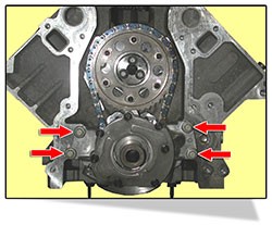
The Right Way To Use Adjustable Checking Pushrods to Determine Correct Pushrod Length -
To determine the correct rocker arm geometry when using an adjustable checking pushrod on a stud mounted rocker arm cylinder head and a mechanical lifter cam, do the following: Mount the complete cylinder head assembly on the engine, including the head gasket. The cam needs to be installed with the lifters that will be used in the engine. Mark the end of the valve stem with a marking pen or Dykem. Install the adjustable checking pushrod and the rocker arm. Adjust the pushrod so the rocker arm is as low as possible with the bottom of the rocker arm .060” above the hex of the stud or guideplate (whichever is closer). Set the valve lash to the recommended setting and lock the adjusting nut. Turn the engine over by hand until the rocker arm you are working with has moved a complete cycle. Now, remove the rocker arm. The roller tip of the rocker arm will have left a pattern on the end of the valve stem. This pattern of movement should be close to the center of the valve but favoring the intake side of the valve stem. If needed, adjust the length of the pushrod to achieve the correct pattern of movement.
The same process can be used with hydraulic lifters, but make sure the lifter is pumped up solid with oil. The pushrod seat in the lifter should not move. After one or two rotations of the engine, check to be sure the seat has not moved. If so, pump it up and continue your procedure. Once the correct length is determined, you can order the correct pushrods and maybe a couple of spares.
· Coil Bind -
mSome things are just forgotten or not worried about. Your valve spring can be one of these forgotten parts. Whether it’s a new cam install, a new valve job on an old engine, a change in rocker arm ratios, new heads, etc., you should always make sure that your combination works for the part(s) you install. First of all, find out what is recommended for the part(s) you are installing, then take some measurements like “Installed Height” of the springs you have, “Coil Bind” height and the I.D. and O.D. of the spring seat. If you insist on using the springs you have, you will still need to know where the springs coil bind and what spring pressure range you should be in so that you will not have “Valve Float” (too little spring pressure in this case) or “Coil Bind” (coils are actually smashing together). Once you have your installed height and you know your coil bind height, make sure that you have at least .060“ extra cushion before coil bind. This way you will have enough room for the spring to travel safely without the spring breaking or coming apart from being overworked. To find this out, you will need to subtract your “Lift at the Valve” and .060” from your installed height. (Example: 1.700” installed height / coil bind is at 1.100” / .500” lift at the valve leaves you with .100” extra travel before coil bind. If you have a dual or triple valve spring, you will also need to make sure what the coil bind on the inner spring(s) will be.
Chevy High-Performance Magazine LS1 Project Truck Gains Average 25 HP
VALVE TRAIN TIPS
More On Why Our Unique "ACCELERATED - LIFT" Rocker Arm Geometry Makes More HP!
There has been a great deal of dialog on several web forums pertaining to our "ACCELERATED - LIFT " camshaft lobes and rocker bodies. To set the record straight, this is what we have always maintained.
Here are a couple of questions about our rockers we would like to address.
The first point that needs to be made in answering these questions is that there is no such thing as a constant ratio rocker arm unless you are talking about a very limited range of lift (.150” or less). This is because the pushrod seat end of the rocker and the valve tip end of the rocker are operating through two different distances and their ratio must constantly vary. Traditionally, most rockers have been designed to start the valve off the seat and return it to the seat slowly. (i.e. traditional SBC 1.5 ratio rockers started the valve off the seat at a ratio of 1.4 and did not get to a 1.5 ratio until .350” valve lift). This was because many OE valves were made in two pieces, and quick opening and closing rates could compromise the valve. The use of high quality, one-piece valves has made this a non-issue. Many performance aftermarket companies, including VHP, tried to develop rockers that were as close to constant ratio as possible. For instance, many 1.6 ratio rockers bring the valve off the seat at 1.62; by .250” valve lift, the ratio increases to 1.65 and by .550” valve lift, the ratio comes back to 1.61. Again, the ratio is varying due to the different length of operating arcs of the end of the rocker. VHP “ACCELERATED - LIFT” design causes an “advertised” 1.6 ratio rocker to start the valve off the seat at a ratio of 1.72 and bring the ratio back to 1.60 by .250-.300” net valve lift. This ratio is then maintained through the rest of the lift profile until the valve is within .250-.300” from going back on the seat. It is then returned to the seat at a ratio of 1.72. This geometry is illustrated in this diagram.
Benefits of this geometry include more flow into the cylinder earlier in the cycle, quicker closing of the valve to trap cylinder pressure before combustion, more effective duration at .200” net valve lift while maintaining a relatively short seat-to-seat timing, and less valve spring seat pressure required because of the mechanical advantage of the higher seat ratio.
During development testing and now corroborated by more than ten years of field-testing in competition, we have not seen any indication that the “Accelerated-Lift” geometry contributes to any additional valvetrain problems in any way.
“Accelerated-Lift” rocker body geometry causes the rocker arm to be a dynamic component in the opening and closing rate of the valve. Some people who don’t seem to understand this think it is “unnatural” to cause the valve to open faster than the cam lobe dictates, but OHC designs with finger followers have been doing it for years. After all, aren’t we interested in what the valve is doing relative to the piston position? Who cares how we get the valve there at the right time? The point is that “Accelerated-Lift” rocker geometry will broaden the torque curve (torque x RPM/ 5252 = HP!!!) of any cam you use it with. Our only warning: Super Stockers and others running extremely tight piston-to-valve clearance should check this with “Accelerated-Lift” rockers. Try ‘em; we know you’ll love ‘em!!
VHP and Leading valve train companies have been working with each other for many years. Together, we have strived to provide the very best products we can with the latest technology available. We think, we design, we manufacture, we test....then we market the product. It seem "Accelerated-Lift" that there has been much confusion about "Accelerated-Lift" cam lobes and "Accelerated-Lift" rocker bodies. We claim that the use of the "Accelerated-Lift" lobes with the "Accelerated-Lift" rocker bodies results in "effective valve lift" durations @ .200" valve lift equal to most other cam/rocker combinations using cams with 4-8* more duration at .050" cam lift. This is the result of the "Accelerated-Lift" Rocker body design. We do not state that our cam lobes (by themselves) give this advantage. The same laws of physics that limit every other cam designer limit our cam lobe designs. We attribute the advantage in valve lift to the "translation" properties of the varying ratio design of our "Accelerated-Lift" rocker body design. If you don’t believe us, test any cam lobe (Crane, Comp, Cam Motion, etc.) with stock LS1 rockers. Install a dial indicator on the retainer and a degree wheel on the crank. Plot a lift vs. degrees of rotation curve. Then install the "Accelerated-Lift" LS1 1.7 rockers (with the pushrods in the rocker kit) and plot the same curve. Measure the duration at .200" net valve lift. The "Accelerated Lift" rockers will definitely provide more duration at this checking point. The reason for this is that, contrary to popular belief, the stock LS1 rockers are only 1.7 ratio above .480" valve lift. They actually start the valve off the seat at a 1.54 ratio. What do you think that ratio does to a "super fast" cam lobe? Slows it down quite a bit? The "Accelerated-Lift" rockers, properly installed, bring the valve off the seat at 1.79. Doesn’t take a math wiz here to see what combination is going to get open quicker and longer!! If you really want to see something interesting, take two lobes that have identical .050" seat-to-seat timing, identical .200" lifter rise timing, but one provides .583" valve lift with 1.7 ratio and the other providing .551 lift with 1.7 ratio. Plot a lift vs. duration curve with any rocker you want, and measure the duration at .200" valve lift. Then do a plot of the .551 cam with our VHP 1.8"Accelerated-Lift" rockers (this will net out .583 also) and measure the duration difference at .200" valve lift. You will be impressed by how much more this second plot gives over the first. It’s also quicker on the drag strip! We’ve done this. Every person reading these threads can do something like this.
Our point is that the only thing that counts is what happens at the valve and the overall rocker ratio is fundamental to this. Contrary to popular belief, there are no fixed ratio rockers on the market (this is because the valve tip end and pushrod seat end operate on two distinctly different arcs). This is why some rockers add power and some don’t. VHP has elected to do extensive development with rockers as a supplement to the lobe. The quickest lobe in the world doesn’t mean diddly if you are using slow acting rockers! Like everything else, it’s the combination that counts. FYI, the higher opening and closing ratios actually allow lower seat pressures because the mechanical advantage of the ratio helps maintain proper lifter preload! Check it out. This isn’t smoke and mirrors; it’s applied geometry and it works!! Roger Vinci
Quiet “ACCELERATED-LIFT’ Roller Rockers Are A Solid 25 HP Increase For LS1 / LS2 / LS6 Engines!
· All of our LS1 rockers use “barrel-shaped” roller bearings to allow more room for oil between the bearings to cushion the load and minimize the “sewing machine noise” common to most roller rocker arms. The sewing machine noise is a noise that the knock sensor can interpret as detonation. When this happens, the computer pulls timing out of the engine in an effort to eliminate the “detonation.” The retarded timing costs horsepower. VHP LS1 rockers are “quiet” to maximize performance without disabling the knock sensor (a performance “trick” that can destroy an engine).
Electronically managed engines require “quiet components” and “innovative component designs” to provide significant performance increases compatible with the vehicle’s operating system. VINCI HI-PERFORMANCE understands this and is working passionately to deliver the best valve train and electronics products for you and your customers.
Our Tech Department is asked for cam recommendations literally hundreds of times a day. Many people frequently ask, “What is the most important factor in making the proper cam selection?” The most important factor is listening to the customer to determine what he/she wants from their vehicle. Next to that, however, comes engine size, final drive ratio, tire size, vehicle weight and transmission type. Engine size (including compression ratio and component types) is obvious, but most people do not appreciate the importance of the other factors in determining proper cam selection. Operating under the assumption that most people want to maximize the performance of their vehicle (as opposed to just operating the engine at as high an RPM as possible), the tire size, combined with the final drive ratio, will determine the engine speed required. For instance, a vehicle with a final drive of 3.42:1 and a tire diameter of 26” will only see about 5400 – 5600 RPM through the lights in high gear in a quarter mile run. Selecting a cam that will make maximum power in the 2500 – 5600 RPM range will provide the best ET. MPH might be higher with a bigger cam, but ET will suffer. This is because MPH is related to peak horsepower, but ET is related to best average torque in the RPM range. Heavier vehicles require a cam with more low end torque than lighter vehicles because it is much more difficult to get a heavier vehicle moving. Automatic transmission vehicles require a camshaft that has idle and low RPM characteristics compatible with the torque converter to be used. Stick shift vehicles must have attention paid to the first gear ratio and the average RPM drop between shifts.
Many people mistakenly think other engine modifications are more important, but this is false thinking. The camshaft is the “gatemaster” to the flow into and out of the cylinder, but this and all of the other engine components must be matched to putting the power in the RPM range that the drivetrain can use. Once the camshaft is selected, modifications to components on both the intake and exhaust must complement the system. It is no good to have a high flow intake system (large throttle body, high-flow intake manifold and custom cylinder heads) if the exhaust can’t get rid of the combustion products. Proper cam selection takes years of real world experience, which often resulted in as many failures as successes. Let’s face it, you often learn more from your failures than your successes. At VHP, the people on hand to answer your technical questions have combined experience in the performance aftermarket of over 100 years! Call us with your questions; someone around here either knows the answer or knows where to get it!
There are many parts in the internal combustion engine that can affect engine performance and fuel economy. The primary part is the camshaft. Cam lobe design directly affects valve train performance (the mechanical movement of the valves), which determines optimum horsepower and fuel consumption. Cam lobe design (shape), dowel pin timing and lobe-to-lobe phasing are camshaft properties used to increase engine horsepower or fuel economy. Increasing both is ideal. Cam lobe shape is determined by lift, duration, acceleration, velocity and cam jerk, as related to its intended usage.
Lobe Separation - Lobe separation is the distance in camshaft degrees that the intake and exhaust lobe centerlines are spread apart. This separation determines how peak torque will occur within the engine’s RPM and power range. Tight lobe separations, such as 108° or shorter, will cause the peak torque to build earlier in the RPM range and peak-out in a short amount of time. Broader lobe separations, such as 112°, will start making that torque peak later in the RPM range, but this allows the torque to build over a wider RPM range. Broader separation angles produce increased idle vacuum for more stable, cleaner, idles and better low end performance. They allow for easier tuning, as well.
Lift is the distance from the cam lobe base circle to the highest point on the cam lobe.
Velocity is the rate of change of lift expressed in inches per degree. Two of its uses are to define how fast (degrees of rotation) lift deviation can occur on quality checks and to track the contact point between the follower and cam.
Acceleration is the rate of change of velocity and is used to determine inertia loads on the cam and valve train.
Jerk is the rate of change of acceleration and is an indicator of how fast inertia loads are applied.
Dowel pin timing is the radial relationship of the camshaft to the crankshaft installed in an engine (assuming that the crankshaft and timing set are properly manufactured).
As to the process of cam lobe-to-lobe phasing. Lobe phasing considers the lifter bank angle (the angle of the lifter bores to the engine’s vertical centerline, as in a “V” type engine) and the required activation (timing) of the intake and exhaust valve within each cylinder. Normally, the bank angle is a given for a particular engine configuration (Ford, Chevrolet, Chrysler, etc.), while the valve timing can be altered to gain horsepower or fuel economy.
The Original Equipment Manufacturer (OEM) determines the original lobe centerline. For example, for a stock small block Chevrolet engine, the valve centerline may be 112 degrees, meaning from the time the exhaust cam lobe is at top dead center (straight up, maximum lift), the camshaft would need to be rotated 112 degrees to bring its intake cam lobe to top dead center for any one particular cylinder. Since nothing is perfect all the time, a tolerance to this specification of 112 degrees is applied - +/- 0.25 degrees or 15 minutes. This tolerance is applied to all branded and private label camshafts. OEM customers may specify something different, i.e., +/- 0.5 degrees.
VHP grinds our camshafts on Cam-O-Matic and Berko CNC Machines. The lobe master tooling used (pattern) is uniquely different for each department. The Cam-O-Matics use gangmasters, while the Berkos use individual plate masters. Gangmasters are one solid piece of steel billet with as many lobes on it as the camshaft to be ground (possibly including the fuel pump lobe). The dowel pin and valve centerline timing requirements are built in to this tooling, which is manufactured and heat treated right here in the USA. The plate master is the shape of one cam lobe; the operator will orient the plate master to generate the dowel pin location and valve timing of each lobe as specified.
Upon completion of producing this tooling, using a variety of precise NC machines in temperature-controlled “clean room” environments at their facility, it is checked on their Adcole-911 cam checking instrument. Both shape and cam lobe centerline are checked, as well as size, concentricity and shape. Upon passing this inspection, the tooling is released to production for use.
Using this tooling, they control the lobe shape and centerline accuracy with accurate repeatability, time and time again.
A Matter of Degreeing-in, And Of Lifters! When degreeing a camshaft, be sure to use the same type of lifter that the camshaft is designed for. You cannot properly degree a flat tappet camshaft by using a roller lifter, and neither can you degree a roller tappet camshaft by using a flat faced lifter. This error does occur with some frequency, so be sure that you ask this question if a customer has trouble when checking their VHP camshaft.
Cams For Stroker Motors - Don’t forget that when you go to a larger cubic inch that the motor is going to have its RPM range shifted downward because of the cubic inch increase. So to get the same RPM range you had, you should increase both cam lift and duration. If you need increased torque, stick with the cam you ran previously to get the benefit of the increased low-end torque. Of course, if you need to discuss any of these problems or are “just plan lost” trying to choose the right cam profile, call us at (407) 478-VETT. We’d be happy to help you select the cam that’s best.
Pushrods
- If you’re looking for more power and the full lift of the cam that you have,
you must realize that
your pushrods will flex under heavy loads (spring pressure, cam
profiles, etc.) and RPM. This can and will happen on any style cam from a
relatively mild hydraulic flat tappet to a mechanical roller. When pushrods
flex you lose valve lift… and horsepower! To reduce this lift-robbing flex, we
recommend that you use the heaviest pushrod wall you can find (.060” - .080” is
the norm to buy). The wall thickness will help stiffen the pushrods and keep
the pushrod flex to a minimum. This allows the valve to get the full lift of
the cam without as much flex. We offer one-piece pushrods in .050” length
increments with .080” walls in 5/16” from 6” – 8.950” in length and 8.200” – 11”
in 3/8” diameter.
CLUTCH
SHIELD INSTALLATION INFORMATION TIPS
Undo the bottom of both front shocks. Loosen the four cross member bolts. Drop
the rear of the motor as far as possible. Remove the bell-housing. Install the
clutch shield and bell-housing at the same time. Allen head bolts help ease the
installation. They are available at most hardware stores.
The Right combination - Your compression ratio is one of three key factors in determining the engine’s cylinder pressure. The other two factors are camshaft duration at .050” lifter rise and the position of the cam in the engine (advanced or retarded). The result of how these three factors interact with one another is the amount of cylinder pressure the engine will generate. It is important to match the engine’s compression ratio with the cam you are selecting. Too little compression (or too much duration) will cause cylinder pressure to drop. This will lower the power output of the engine. Too much compression (or too little duration) and the cylinder pressure will be too high, causing pre-ignition and/or detonation. You will then run less ignition timing and lose power.
Extra Cylinder Pressure A Good Thing?
More cylinder pressure is always a good thing, right? Wrong!! Cylinder pressure (measured with a gauge inserted in the spark plug hole) is a result of the interaction of compression ratio, the camshaft duration at .050 lifter rise, and whether the cam is degreed in advanced or retarded position. If, as an example, the compression ratio is too low and the duration of the cam is too long, cylinder pressure will drop, robbing the engine power. If the compression ratio is too high and the duration is too short, the cylinder pressure will be too high, causing premature ignition and detonation. Both of these conditions can damage costly engine components. That’s why it is so important to know what compression ratio your engine has before selecting a new cam.
Keep in mind that the cylinder pressure will also dictate what octane rating of unleaded fuel you must use for optimum performance. If your compression ratio is above 10.5:1, chances are you will have to use an octane rating of 93 or higher Pressure readings above 165 psi may require racing fuel or a suitable additive. Remember, too much octane slows the burn down like reducing timing. This can hurt power. Match the octane to the cylinder pressure and the timing curve.
Recently, we’ve had customers think they have had a valve train problem at high RPM conditions, and they have called us with cam lobe or valve spring questions. When discussing their problem, we have found that their fuel injection systems were not up to supplying enough fuel to provide the horsepower their engines were capable of making.
Keeping in mind the “old rule of thumb” that it takes 0.5 lbs of gasoline per hour to make 1 HP (this is referred to as the Brake Specific Fuel Consumption-BSFC); a 600HP engine will require approximately 300# of gasoline per hour. Fuel injectors are rated at a certain # of fuel/ hr (ex. 48#/hr), but this is a free flow rating at a specific fuel pressure. If the pressure is higher, flow will be higher and if fuel pressure is lower, fuel flow will be lower. Also, in operation, a fuel injector must be turned off at least 10% of its operating cycle (duty cycle). That means that a given injector of say 48#/hr flow rating will only flow about 43#of fuel per hour (because 10% of its free flow capacity is lost during the “off” time of the duty cycle).
If we want to make 600HP and we have 8 injectors with a 48#/hr flow rating (43#/hr at 90% duty cycle), we have the injector capacity of 344# of fuel/hr (8 x 43#/hr). This gives us the capacity to make approximately 688HP if our tuning is in the ballpark. To be on the safe side, we recommend fuel injectors that would provide the necessary fuel flow at 80% of their free flow rating. For example; if we want to safely make 600HP, and our BSFC is .500; then we need 300# of fuel out of 8 injectors (37.5#/hr at free flow). If the injectors are to operate at no more than 80% duty cycle, we need to have 47-48# injectors (37.5 #/hr / 80% = 47#/hr). If your tuning is good and BSFC is less than .500, then you can have slightly smaller injectors (although you probably would want the safety of the larger injectors). If your BSFC exceeds .500, you will need higher flow injectors.
NOTE: The only reason you would want to keep the injectors on the small size would be for good idle and low speed driving characteristics if that was an operating requirement for the engine. If very high horsepower and good low speed operation is necessary, you might have to consider two injectors per cylinder with proper computer control of each injector; one for low speed and both for full throttle. Also, assure that the fuel pump is capable of feeding the injectors at the proper fuel pressure!
Proper Coolant Temperature and Camshaft Life!
Have you ever tried to find what proper coolant temperature is for most automotive engines? There are a lot of people who think they know, but it is difficult to find specifics, even in textbooks. We know we want the intake air to be as cold as possible (for best power) because cold air is denser (there are more oxygen atoms per cubic foot). The coolant temperature, however, is a different matter. The internal combustion engine changes chemical energy stored in gasoline into heat energy that is focused on the piston tops. If the cylinder heads and engine block are too cold, they will absorb much of the combustion heat before it can be used to push the piston down the cylinder. If the engine gets too hot, engine lubricants can break down, as well as overheating of the intake charge can lead to detonation, etc.
It turns out that coolant (usually a 50/50 mixture of coolant and water) has some fantastic properties that are ideal for use in engines. With a properly pressurized cooling system, coolant will not freeze until –30°F, and it won’t boil until +270°F (new oils don’t start to break down until well over 270°F). With these characteristics, engine designers have decided that engines should operate at approximately 210-215°F. Why, you ask? Well, it has to do with operating the engine at a high enough temperature to boil water out of the oil after the engine is cold started. If you have dew on the grass, it is certain that you have water in your oil, as the crankcase is open to atmospheric pressure! You can either remove the water by draining it out the bottom of the oil pan (remember the oil floats on water) or run the engine long enough and hot enough to boil the water out of the lubrication system. Years ago, coolants weren’t as sophisticated and engines were run at 165-180F, but the oil was changed every 1000 miles or so. That’s why many old timers think engines should run at 165-180F. Have you ever noticed that Ford doesn’t put temperature marks on their gauges? They just mark C for cold and H for hot and write “normal” through the center. If you hook up a scan tool to a GM, you will often find that the gauge reads much lower than the coolant temp sensor. That is because they know most drivers don’t understand how hot an engine should run.
So what does this have to do with camshafts? Many enthusiasts erroneously think that the colder their engine runs the better! If they are not running the engine hot enough to boil the water out of the oil, the oil becomes contaminated and the lifter/cam lobe interface is the highest load point in the engine. Engines running too cool can contribute significantly to camshaft and lifter failure. Think about it: What good does it do to use the most expensive synthetic oil and then run the engine so cold that it is contaminated by water vapor??!! Another point, piston manufacturers’ piston-to-wall clearance recommendations assume you will be running the fully warmed engine at 200°+F. Run the engine too cold, and you could see some scuffed pistons because the cylinders had not expanded enough to provide clearance.
If your engine will only run its best at the drag strip with the engine at 165°F, you probably have too cold of a spark plug heat range and you are probably jetted way too rich! If you keep the engine hot (not the intake charge), you will be using more of the heat energy in the gasoline to make power instead of just heating up your block. It does take “tuning know-how” to run an engine at 200-210°F, but you might be surprised how well and how long it runs when you do!! One final point - running a computer managed engine at 165°F compared to the factory 210°F will often cost you as much as 4 MPG. The reason for this is that the computer thinks that the engine is not off the “choke cycle” and it is still putting out a rich mixture! Check the science on this and don’t pay attention to the “old wives tales” of the past. Materials and lubricants are much better and different today than they were in the past!!